Now you are ready to transfer the title block and frame from the model sheet to the layout sheet. First, let's move the frame, since it is a simple rectangle.
1. If the mode is turned on MODEL, click on the corresponding indicator button in the status bar to switch to the paper space mode, that is, the layout sheet editing mode SHEET.
2. Launch the tool Rectangle, for example, by entering in the command window rectangular.
3. When prompted to set the coordinates for the first corner, enter 0.0.
4. AutoCAD will prompt you to set the coordinates of the second corner. Enter 408.4, 572.4. A rectangle will appear on the layout sheet (Fig. 13.7), the dimensions of which correspond to the dimensions of the printed area, represented by dashed lines (compare Fig. 13.7 with Fig. 13.5).
Rice. 13.7 Rectangle matching the printable area
Advice. Each printer or plotter has a different printable area, which may depend on the selected format. To find out this size, right-click on the Sheet1 shortcut and select the command from the context menu that appears Sheet Settings Manager and click in the window that opens Sheet Settings Manager on the button Change(see Fig. 13.4). In the window that appears Sheet Options – Sheet1(see Fig. 13.3) click on Properties button, which is to the right of the selected one in the list Name printing devices. A window will appear on the screen Plotter Settings Editor. Go to the tab Device and document, expand the parameter group Non-standard formats and calibration and select the option Change. Find the area in the list at the bottom of the window Changing standard sheet sizes format you need, and below the list in the text area Changing standard sheet sizes you will see the size of the printable area for the selected printing device and the selected format (Fig. 13.8). Then close all windows by pressing Esc several times.
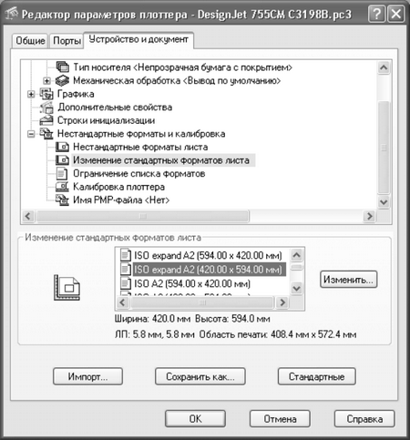
Rice. 13.8 Window Plotter Settings Editor allows you to find out the size of the printable area for the selected format and printing device
5. It is necessary to shift the line of the resulting rectangle inward by 1 mm so that the frame lines are printed. Use the command for this Similarity, and then delete the original rectangle.
6. Break the rectangle into separate segments using the command Dismember, and then move the left vertical line inward by a distance that will provide the desired inner size of the area covered by the frame. This size can be calculated using the formula Wpa – 2 × 1 – (Wf – (5 + 20), where Wpa is the width of the printed area, and Wf is the width of the format. Substituting the values for the selected format and plotter into the formula, we get the offset value equal to 408.4 – 2 × 1 – (420 – (5 + 20)) = 11.4 mm.
7. Remove the original vertical line, trim the extra horizontal segments using the command Trim and merge the new line with the rest of the frame lines using the mode Close teams Polred.
8. Run the command again Polred, for example, by entering prd or simply press Enter to repeat it, and select the resulting rectangle. Enter Width or simply w to enter polyline width mode, then enter 1 to make the polyline 1mm wide.
9. Press Enter to complete the command Polred.
10. Go to the Model sheet by clicking on the tab of this sheet.
In today's lesson we'll talk about the Sheet space in AutoCAD, creating new sheets and working with them.
AutoCAD provides two workspaces for working with drawings. This Model and Sheet space. All constructions are made in the model. And paper space in AutoCAD is used to layout the drawing before printing.
At the same time, it is convenient to draw all objects in model space with a scale of 1:1, and then scale and design the drawing on sheets. There are, of course, some peculiarities here. But we will look at them in another lesson.
The transition to the sheet is carried out using bookmarks under the graphic area of the drawing. You can create multiple sheets with different layouts. But by default, there are always two of them created - Sheet 1 and Sheet 2.
When you go to one of the sheet tabs, a dialog box usually appears Sheet Preset Manager. Serves just for setting up sheets before printing.
Close it for now, we'll look at it in the next lesson.
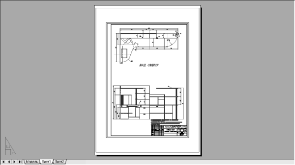
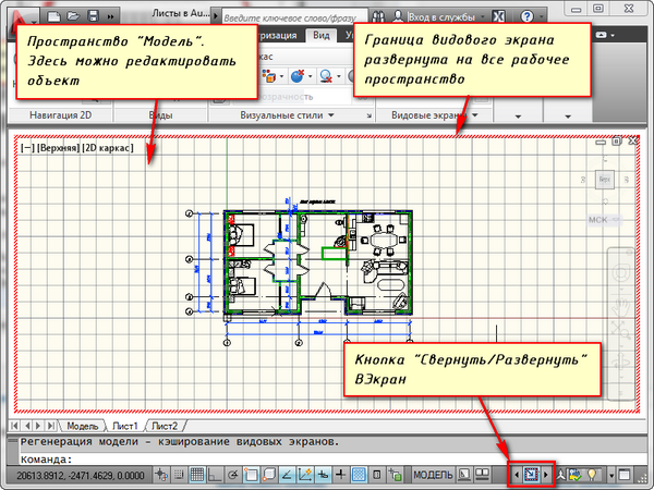
Now we have in front of us a white sheet with a dotted frame and a rectangle containing our drawing.
So... The white sheet is our sheet of paper on which everything will be printed. The dotted frame defines the visible print area. A rectangle with a drawing inside is viewport.
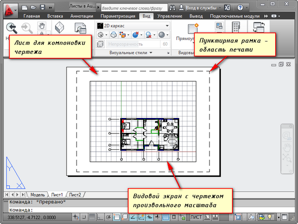
Viewport- this is a kind of fixed view of the drawing or part of it from the model space. Moreover, it is possible to fix different types the same objects, for example, a floor plan with load-bearing walls and partitions or floor plan with load-bearing walls only. These types can be placed on one sheet or on different ones. This is a very big plus in using sheets in AutoCAD.
By default, one viewport is already created on the sheet. And the drawing from the model space is presented in it at an arbitrary scale.
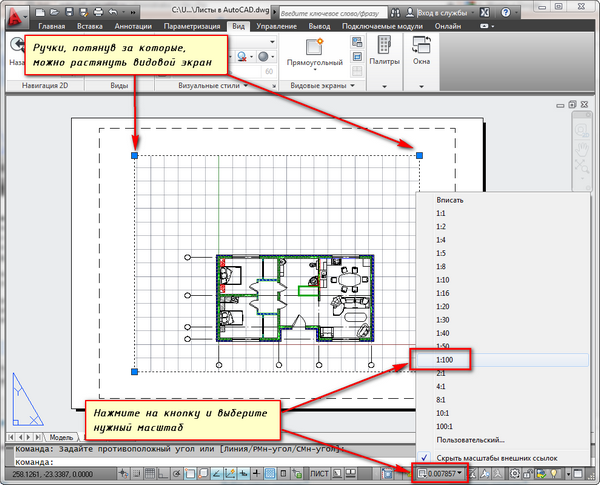
The viewport rectangle itself can be enlarged or stretched using handles. And then choose the scale with which the drawing should be presented on the sheet. To do this, select the viewport and set the desired scale. For my example I will take 1:100.
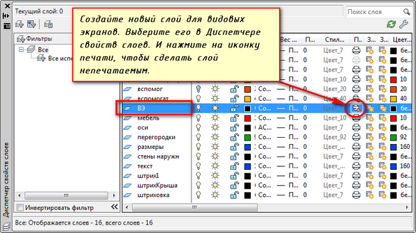
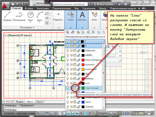
The layer containing the viewport rectangle can be made non-printing. In this case, the frame itself will remain visible on the sheet, but when printed on paper it will not be visible. To do this, create a new layer with a name, for example, VE. And click on the print icon in Layer Properties Manager.
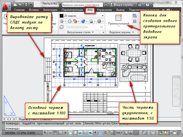
It is convenient to first place a frame with a stamp on the sheet, fill out the stamp, and make some inscriptions. Then enter the drawing with the desired scale using viewports.
If you need to show some node of an object on the same sheet, then there is no point in drawing it in the model again with an enlarged scale. It is enough to simply create another viewport and display this node on it with a different scale.
True, there will be some difficulties with the so-called out-of-scale elements. This is text, line types, shading, dimensions, etc. But more on this in the next part of the article about working with sheets in AutoCAD.
Here is my example with a drawing on a sheet. I took the frame from the SPDS module, which can be downloaded and installed from the Autodesk website.
Another handy use of sheet viewports is the ability to freeze individual layers.
Let's go to the viewport. To do this, double-click the left mouse button inside the viewport frame. It is highlighted with a bold line.
And now you can edit the object here.
Those. You are currently in model space. For convenience, you can expand the viewport border to cover the entire workspace. To do this, click on the “Expand VScreen” button on the status bar. To return to the sheet, click the "Collapse VScreen" button.
We need to freeze some of the layers. For example, internal partitions. Click on the layer freeze icon. And the layer seems to disappear. But it only disappears in the active viewport. In the new screen it will already be visible.
HOW TO CREATE A NEW SHEET IN AUTOCAD?
Hover your mouse over a tab, for example, sheet 1. And right-click. The menu for working with sheets will open. Here, select New Sheet. Provide a name for the Sheet and press "Enter".
You can also create a new sheet in AutoCAD by entering the RLIST command.
You will be prompted on the command line: "Enter the parameter for the sheet [Copy/Delete/New/Template/Rename/Save/Set/?]<установить>".
In response to it, indicate the key letter for calling the desired option of the RLIST command.
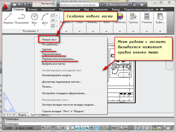
Thus, you can copy, delete, rename sheets.
Now you know how to create a new sheet in AutoCAD. You can also save the sheet with the configured parameters as a template, and then use it in further work.
Before any user AutoCAD The question always arises of whether to use model space or paper space for drawing. Typically, novice users use only model space. As the level of proficiency in the program increases, designers begin to look for ways to speed up and make their work easier. One of the most simple ways Make your work much easier by starting to use worksheets.
There are many ways to organize your drawing work using model and paper spaces at the same time. One of them is to create drawing graphics in the model and design them on sheets using viewports. I propose to consider the benefits that can be obtained from using sheets.
Possibility to draw in natural scale 1:1
Using sheets to design a drawing allows you to draw models in space at a natural scale of 1:1. Having a drawing in real scale in the model space, we can always use viewports to create a drawing on a sheet at any required scale without rebuilding the original drawing. Changing a drawing in the model will automatically update the drawing on all sheets.
Easy control over the drawing scale
For new and already created viewports, you can easily change the scale using the drop-down list of preset values, or set your own value
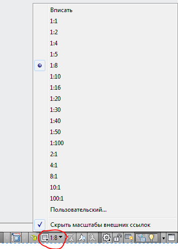
This, again, eliminates the need to change the drawing in model space; its original scale will remain unchanged.
Placing different parts of a drawing on one sheet
With the help of viewports, we can arrange parts of the drawing on the sheet in a way that is convenient for us. At the same time, the drawing will remain a single whole in model space. Also, if there is a need to create a detailed view on a scale larger than the main drawing, then this can be easily done in a sheet using a viewport with a border along the object. If you work only in model space, then creating a detailed view is possible only by copying the required part of the drawing, removing unnecessary elements, and scaling to the required size. At the same time, if there is a need to change the main view, the detail view will have to be redone. A sheet with viewports allows you to avoid such routine work.
Different orientations of the same image on different sheets
Each viewport can have its own rotation angle, allowing you to create different drawings. For example, on the bottom drawing the image of the object will be with a horizontal orientation, and on the second - with a true orientation to the north, as on the general plan.
Different views of a drawing on one sheet
In AutoCAD, in the Layer Manager, you can configure the display options for each layer in each specific viewport. This allows you, for example, to hide part of an image in a drawing view by simply turning off certain layers, or to display hatching in a detail view but hide it in the main view. This is a huge help in preparing drawings.
Using annotative scales
Even if you want to design a drawing in model space, for example, add dimensions and labels, it still makes sense for you to use sheets. Using annotation scales, you can display your drawing on a sheet at different scales, while the size of annotative objects (dimensions, labels, etc.) will remain unchanged. This will avoid the problem like in the picture
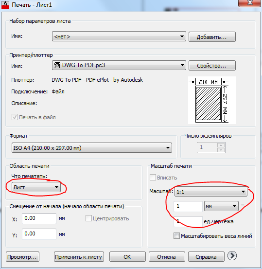
Easy printing
Printing from paper space is a very basic task. When running the command Seal in the settings window it will immediately be determined that you need to print the sheet at a scale of 1:1 (you do not need to select the print area and select the scale and position on the sheet, as you need to do when printing from model space). Just press the OK button and go to the printer to get a print!
Possibility of using binders
Sheet Set Manager is a great tool that allows you to manage drawings within an entire project. Sheets of drawings from several files can be included in one binder. Sheets do not work with data from model space, only with sheets, so only those who use sheets in their work can appreciate all their advantages.