Or the Tesla transformer, as it is otherwise called. Videos used from the YouTube channel Alpha Mods. The article contains three videos and a simple diagram of this device. The first video is about assembling the circuit, the second is about the case and testing the device. The third is effects. It is profitable to purchase radio components in this Chinese store.
This project will require a lot of winding wire. But you don't need to buy it at all. Use wire from transformers installed in power supplies, which, as a rule, lie unnecessarily at home. One of the coils has a thick but short wire. On the second coil the wire is thinner, but much longer. The primary winding is 0.2 mm, the secondary is 0.6 mm.
To get the wire, you need to disassemble the transformer by knocking on the housing. So the varnish is destroyed and the transformer falls into pieces. Now after the tape layer we see the winding wire.
We will wind the coil on a plastic pipe. Its size is 140×22. First, we need to make calculations to find the required length of wire that will be wound around the pipe. Calculations showed that we need to wind 31 meters of wire to get 450 turns on this pipe.
On the desktop, measure a distance of 1 meter. This is for measuring the wire. To wind the coil, you can build a device that will make the process semi-automatic. But, if you don’t mind your time, all this can be done manually.
Assembly
Notice that the plus goes through two places. First, it passes through a resistor and goes to the transistor. Secondly, it goes to the coil, and after it again goes to the transistor.
Kasper housing and Tesla coil testing
This container has a lid and a silicone gasket on it. The container will be upside down. Now you can make markings for future parts and make holes for them. On the side there will be a power connector. Given the soft material of the container, holes can be made very easily.
An elastic band is used to secure the reel. It will be put on the reel and pressed to the bottom with a nut and washer. Now the reel sits perfectly in its place and at the same time has the ability to be slightly cushioned. We will pass the wires inside so that it is unnoticeable.
The primary coil can be wound in different ways. The legs can be made from small metal spikes. The Tesla coil will definitely need cooling, so that also needs to be done.
Lastly, repainting and finally assembly. A layer of thermal paste is applied to the transistor, and it is placed on the radiator. For the torus, a ping pong ball and foil are used. You need to wrap the ball in foil. The most important thing is that the secondary coil wire touches the torus.
The power supply from an old 32 Volt printer was used.
Eventually the box is closed and the project is officially finished. This device can be used to transmit energy wirelessly. It is almost impossible to control this energy with this device, but you can play with it. For example, hold 220 volt light bulbs in your hands, which will burn by receiving electricity through the air. You can turn off the light on the table with one touch of your hand.
More effects of the assembled Brovin kacher
Attention! The site administration is not responsible for the content of methodological developments, as well as for the compliance of the development with the Federal State Educational Standard.
- Participant: Pishchulin Andrey Alexandrovich
- Head: Truntaeva Svetlana Yurievna
Introduction
At least once in our lives, we hear on TV or on the Internet about the great genius Nikola Tesla and his coil, which can transmit electricity through the air. But no one thought that at home you could assemble a similar device called the Brovin Kacher. In my work I want to show how you can use electrical appliances that are not connected to the network, and I will prove that this can be done at home without much expense.
Relevance The topic is due to the fact that the problem of finding clean energy in the 21st century is acute. In the modern world, humanity needs electricity every day. It is needed both by large enterprises and in everyday life. A lot of money is spent on its production. And that's why electricity bills are rising every year.
Object of study: physical phenomenon of contactless energy transfer.
Subject of study: a device that can transmit electricity wirelessly.
Hypothesis: Kacher Brovina can be assembled at home with minimal cost.
Target: make a working model of the Brovin Kacher and consider the possibilities of its practical application.
Tasks:
- study reference and scientific literature on this topic;
- consider the device, principle of operation and application of the Brovin kacher;
- create a working model of the Brovin quality player;
- analyze the knowledge gained on this topic.
Research methods:
- working with methodological literature
- comparative analysis
- observation
- experiment
Chapter I. Theoretical part
1.1. The device and principle of operation of the Brovin Kacher
The Brovin Kacher was invented in 1987 by Soviet radio engineer Vladimir Ilyich Brovin as an element of an electromagnetic compass. Engineer Brovin V.I. Higher education – graduated from the Moscow Institute of Electronic Technology in 1972. In 1987, he discovered inconsistencies with generally accepted knowledge in the operation of the electronic circuit of the compass he created and began to study them. He made many inventions at home. One of them is Kacher Brovina.
Let's take a closer look at what kind of device this is. Brovin's kacher is a type of generator assembled on a single transistor and operating, according to the inventor, in abnormal mode. The device exhibits mysterious properties that date back to the research of Nikola Tesla. They do not fit into any of the modern theories of electromagnetism. Apparently, Brovin's kacher is a kind of semiconductor spark gap in which the discharge of electric current passes through the crystalline base of the transistor, bypassing the stage of formation of an electric arc (plasma). The most interesting thing about the operation of the device is that after a breakdown, the transistor crystal is completely restored. This is explained by the fact that the operation of the device is based on reversible avalanche breakdown, in contrast to thermal breakdown, which is irreversible for a semiconductor. However, only indirect statements are given as evidence of this mode of operation of the transistor. No one, except the inventor himself, has studied the operation of the transistor in the described device in detail. So these are just assumptions by Brovin himself. So, for example, to confirm the “black” mode of operation of the device, the inventor cites the following fact: they say, no matter what polarity the oscilloscope is connected to the device, the polarity of the pulses shown by it will always be positive.
Maybe kacher is a type of blocking generator? There is also such a version. After all, the electrical circuit of the device strongly resembles an electrical pulse generator. Nevertheless, the author of the invention emphasizes that his device has a non-obvious difference from the proposed circuits. It provides an alternative explanation for the occurrence of physical processes inside the transistor. In a blocking oscillator, the semiconductor periodically opens as a result of the flow of electric current through the feedback coil of the base circuit. In quality, the transistor must be permanently closed in a so-called non-obvious way (since the creation of an electromotive force in the feedback coil connected to the base circuit of the semiconductor can still open it). In this case, the current generated by the accumulation of electrical charges in the base zone for further discharge, at the moment the threshold voltage value is exceeded, creates an avalanche breakdown. However, the transistors used by Brovin are not designed to operate in avalanche mode. A special series of semiconductors has been designed for this purpose. According to the inventor, it is possible to use not only bipolar transistors, but also field-effect and radio tubes, despite the fact that they have fundamentally different physics of operation. This forces us to focus not on research on the transistor itself in the quality, but on the specific pulse mode of operation of the entire circuit. In fact, Nikola Tesla was engaged in these studies.
Kacher Brovina is an original version of an electromagnetic oscillation generator. It can be assembled using various active radioelements. Currently, when assembling it, field-effect or bipolar transistors are used, less often radio tubes (triodes and pentodes). Kacher is a reactivity pump, as the author of the invention, Vladimir Ilyich Brovin, himself deciphered this abbreviation. The Brovin Kacher is powered by a modified 12 V, 2 A network adapter and consumes 20 W. It converts an electrical signal into a 1 MHz field with an efficiency of 90%. One of the parts of this device is a plastic pipe 80x200 mm. The primary and secondary windings of the resonator are wound on it. The entire electronic part of the device is located in the middle of this pipe. This circuit is completely stable, it can work for hundreds of hours without interruption. The Brovin Kacher with self-powering is interesting in that it is capable of lighting unconnected neon lamps at a distance of up to 70 cm.
1.2. Areas of use
The widespread practical application of new devices and products operating on the basis of this new physical phenomenon will make it possible to obtain a very significant economic, scientific and technical effect in various spheres and areas of human activity.
Let's consider the areas of application of this device:
1. New relays and magnetic starters based on the widespread use of kacher technology:
- can lead to a reduction in energy costs and an increase in production efficiency in general, which together will provide a very significant economic effect in the country’s economy;
2. Devices that illuminate fluorescent lamps (fluorescent lamps) not from 220 V, as now, but using KACHER technology products, from a supply voltage of 5 to 10 V:
- this will significantly reduce the level of fire and explosion hazards
3. Devices that provide the possibility of not serial (currently used), but parallel connection of individual solar battery elements:
- will significantly increase the reliability, durability and efficiency of their operation, as well as obtain a significant economic effect from their use;
4. Devices for inductive transmission of control information and energy between different traffic lights located on different sides of the intersection and included in one traffic light object (without the use of electrical wires currently used for this, with large labor costs for their installation):
- will save energy and costs.
1.3. Negative impact
Despite the positive aspects of using this device, one cannot fail to note its negative impact. While performing this practical work, I noticed that due to the strong electromagnetic field created near the camera, cell phones, cameras, and tablets fail. And here I thought that in addition to the positive aspects, this device has a negative effect, including on the human body. After reading the literature on this issue, I found out that a strong electromagnetic field has a negative effect on the human nervous system. Staying near a working device for a long time causes a headache, and upon close contact, a slight aching pain in the muscles of the arms. In addition, as it turned out, the kacher can emit ozone, which we can feel by the corresponding smell.
Also, do not touch the discharges with your hands; due to the high frequency, a small burn may remain on the skin. Thus, we can conclude that when working with this device it is necessary to follow the safety rules:
- Do not try to touch the discharges with your hands. The pain, if there is any, will not be severe, but you are guaranteed a burn.
- Keep pets away from the device.
- Keep mobile phones and other electronics away from the device.
- You should not stay near the switched on device for a long time.
Chapter II. Practical part
2.1. Assembling the Brovin quality camera installation
Let's consider the stages of assembling this device at home.
Basic elements of Kacher:
- inductor (secondary winding);
- inductor (primary winding);
- pay.
- frame
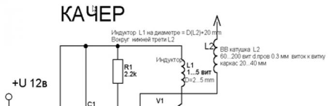
The diagram that I followed during assembly is as follows:

Installation details:
- Polyvinyl chloride (PVC) pipe with a diameter of at least 25 mm and a length of 30 cm (the glow range of the light bulbs will depend on this). I used a pipe with a diameter of about 55 mm.
- To make the secondary winding of the kacher, I used copper wire coated with a double layer of varnish and 0.20 mm in diameter. It should be wound on the pipe, at least 1500 turns. (My copy of the kacher has about 2000 turns wound on it.) Every few centimeters I applied glue to fresh turns, otherwise the winding might get lost and tangled.
- To make the primary winding, I needed a copper wire with a diameter of 0.5 cm, which must be wound around the secondary coil. It is necessary to make about 4 turns. We wind all the windings in one direction! We install and secure the pipe with the winding on plywood or a board, stretch the primary winding by 1/3 of the secondary. The windings must not touch! Then we fuse a metal wire the size of a sewing needle into the pipe from above and solder the end of the winding to it. Next, we screw the radiator for the transistor to the platform next to the coils, coat the base with heat-conducting paste and screw the transistor to the radiator with a metal socket.
To make the board I needed the following radio components:
- throttle,
- non-polar capacitor (1000 v 3000 μ F),
- 2 resistors (2.2 kOhm and 150 Ohm),
- NPN transistor, the more powerful the better (they can be found in a regular PC power supply or on the board of old tube TVs).
Everything is mounted as shown in the diagram (Fig. 1). Solder the power wires.

This device must be connected to a power supply with a voltage from 12 to 38 v, which I also designed myself (Fig. 3)

Checking the quality is carried out by placing a fluorescent light bulb on the secondary winding; if the connection is correct, it will light up. When the secondary winding is touched by a metal object, there will be a discharge between them. If the kacher does not work, then you need to check whether the circuit is assembled correctly or try changing the ends of the primary winding.
2.2. Effects observed during the operation of the Brovin quality camera
Let's consider the effects observed during the work of Kacher Brovin, which I constructed at home.
- We bring a fluorescent lamp to the secondary winding, we see that it lights up. (Fig. 4) If you bring a gas-discharge lamp to the kacher, it also begins to glow. (Fig. 5) The same effect is observed with other similar lamps. You can also see a so-called glow discharge in a regular incandescent lamp. (Fig. 6)


- During operation, the kacher creates beautiful effects associated with the formation of various types of gas discharges - a set of processes that occur when an electric current flows through a substance in a gaseous state. Brovin's quality ranks:
- Streamer (from English Streamer) - dimly glowing thin branched channels that contain ionized gas atoms and free electrons split off from them. Streamer - visible ionization of air (glow of ions) created by an explosive - Kacher field. (Fig. 7)

- Arc discharge occurs in many cases. For example, with sufficient transformer power, if a grounded object is brought close to its terminal, an arc may light up between it and the terminal. Sometimes you need to directly touch the terminal with an object and then stretch the arc, moving the object to a greater distance. (Fig. 8)

Conclusion
Kacher Brovina is an original version of an electromagnetic oscillation generator. In my work, I proved that it is possible to make a working model of a kacher at home, and also considered the possibilities of its practical application. I would like to note that my work in this direction is not finished. In the future, I want to make a Brovin kacher with audio modulation. To do this, you need to complicate the circuit a little by adding two resistors and a transistor. (Fig. 9) Thus, we will be able to play music through the power supply circuit of the camera. In practice it looks beautiful and interesting.

As a result of the research carried out in this work, we can conclude that the Brovin Kacher is a simple device to manufacture and configure. With which you can demonstrate many beautiful and impressive experiments. During the operation of the coil, we observed two types of discharges.
Analyzing all of the above, we can say that Kacher Brovina can be successfully used in alternative energy, for example, in devices for generating free electricity using permanent magnets.
In conclusion, it is necessary to emphasize the following: the creation of new technologies based on the described physical phenomenon can give Russia very significant advantages over other countries. Since, having carried out in the near future all the necessary studies of this physical phenomenon and developed a wide range of new devices and products operating on its basis and intended for wide practical application in various fields and spheres of human activity, Russia can make a new qualitative leap in its further technological development . The introduction of Russian know-how will radically change the entire energy infrastructure and society as a whole - when a new method of generating energy is suddenly discovered and experimentally confirmed.
Hello, dear readers and site guests!
Today we will talk about Brovin’s quality. This interesting device was invented in 1987 by Soviet engineer Vladimir Ilyich Brovin. The kacher was part of the electromagnetic compass, but today it is most often collected for fun. According to Brovin, the scheme is not too complicated, and with its help you can get the most interesting visual effects.
Kacher is a reactivity pump, which is what this device does. According to legend, it produces more energy than it consumes, which is highly doubtful, but not too difficult to verify. One of the most interesting qualities of the kacher is that the Brovin kacher scheme is extremely simple and accessible even to beginners. It can be assembled using or, but radio tubes - pentodes and triodes - are also suitable for this.
The “mysterious” properties that Brovin’s kacher demonstrates go back to the famous research of Nikola Tesla. They do not fully fit into any of the modern theories of electromagnetism, and this is precisely why Brovin’s powerful kacher interested me. In essence, the Brovin Kacher is a kind of semiconductor spark gap, the discharge in which passes through the crystalline base of the transformer, skipping the stage of the appearance of an electric arc. And the most curious thing is that after the breakdown the crystal returns to normal.
The fact is that in such devices it is not thermal breakdown that occurs, but avalanche breakdown. But here it is worth noting that detailed studies of the quality were carried out only by the engineer Brovin himself. After him, such a device was repeatedly assembled by amateurs, but the principles of its operation were not studied. For example, to confirm the status of a quality player, Brovin recommends connecting an oscilloscope to it. Whatever polarity it is connected to, the pulses will always show positive polarity. While Brovin’s kacher scheme has not found any practical application, it has not been subjected to serious research. And amateurs can only explore the simplest manifestations of the work of a caster, which is what we will do next.

I will not dwell in detail on the device diagram, because it is well-known and publicly available. Let me just note that the camera consists of three main parts: the camera itself, the power supply and the breaker. A chopper, or control unit, is used to regulate the frequency and duty cycle of the pulses emitted by the pump. They enter the transistor, which opens and closes the junction between current and source in accordance with the pulse clock. When opened, current flows and closes the pump circuit to the power supply - this creates a pulse. During the short period of time during which the opening occurs, a spark runs through the terminal.
To describe it in a nutshell, we can say that when current flows in two directions to the transistor and the chopper, voltage appears on the power supply. The breaker turns on, sends a pulse to the transistor gate, the gate opens the junction, current passes through the switch and closes the circuit.
So, what do we need to assemble a powerful Brovin kacher?
- Hands - even the most inexperienced or crooked ones will do.
- Wire with a cross-section of 0.25 mm - you can use wire from a transformer.
- Bipolar transistor p-p-p (kt805AM, kt808, kt805B, KT902A and other similar transistors that can be obtained from almost any Soviet electronics.)
- A pair of resistors.
- High capacity capacitor (1000 -10000 uF)
- DC power supply (from 12 to 30 volts with a current of at least 1-1.5 amperes.)
This is the so-called standard set; if you do not have any element, you can always find a replacement for it.
For example, the chopper can be replaced with any generator that produces rectangular pulses. Changing any circuit element values by ten to thirty percent will not prevent the circuit from working. Of course, you should remember that working with other indicators of Brovin’s quality will be somewhat different. I recommend choosing a generator frequency within 150 hertz.
The Brovin Kacher is connected to a regular 220 volt network. For protection purposes, I advise you to install a five-amp fuse. To power the kacher, you will need 310 volts, that is, the 220 volts received from the outlet will need to be straightened. To do this, you can take a diode bridge with indicators of at least ten amperes and five hundred volts. The breaker will need another diode bridge - 50 volts and one ampere. In addition, it must be bypassed with a capacitor.
The Brovin kacher himself may have deviations of parts performance of 20 percent from the nominal ones. The field transient can be replaced with another one, but in this case I advise you to use a similar, but more powerful one. The circuit capacitor will need to be adjusted independently; the optimal adjustment level is from half to one microfarad.
As for the coil, you will need two wires for the windings. For the primary, a wire of two squares is used, but the winding will have very few turns. The secondary winding can be made with PLSHO or any other similar wire. The main thing is to get the required number of turns. Some advise making only 500 revolutions, others say that at least one and a half thousand are required, if not all two. We will focus on the average in the region of a thousand turns. You can use glue, varnish, or epoxy resin to wrap it so it doesn't fall apart if you don't wrap it tightly enough. In any case, a lost winding can greatly hinder you.
We take a choke with a resistance from fifteen to forty ohms. You can remove this from LDS lamps. If you can’t find just such a choke, you can replace it with a resistor whose resistance is within the same limits and whose power exceeds a thousand watts.
Now we begin to assemble Brovin's kacher. First you need to make the primary coil. To do this, take any tube with a diameter of 4-7 centimeters and use a large-section copper wire or copper tube. We make four turns, not too tightly, since after this you will need to remove the tube. Now we remove the tube and stretch the wire so that the height of the winding is ten to fifteen centimeters.
The secondary coil should be three times higher. For it, we take a thin winding wire and wind it around a plastic tube for about 1000 revolutions. I did this by hand, so creating the coil took a little time. If you've ever done this, you know what a tedious process it is. You can speed up the work somewhat by using an electric screwdriver. But in this case, it is very important to calculate the number of revolutions per minute and the time it takes to create the winding in order to make the required number of turns. The reel is ready. To prevent it from going astray, you can apply glue in places - it will hold it in place and allow you to work without extreme caution. We install the primary coil around the bottom of the secondary coil.
We assemble the remaining elements according to the diagram. The tube needs to be fixed vertically, so it is best to glue its lower part to the base. You can take an unnecessary disk for this, but I chose a wooden plank - a more convenient option. Now let's check the diagram. If something doesn’t work, first try swapping the contacts of the primary coil; in addition, the direction of the primary and secondary windings is important - they should be wound in the same direction. If this does not help, check the transistor. It may be faulty. Also check the conductivity of the coils - there may be no contact somewhere.
I also advise you not to be afraid of the position and number of turns of the thick wire - it should be located at the base of the coil, but for me it is almost in the middle. Change its position until the effect appears. This should help, no other problems should arise with such a simple circuit.
Now let's move on to setting up the assembled camera. To do this, we adjust the tuning resistor R1. I installed radiators on the transistors - they get very hot, so it’s better to protect the device from surprises.
This assembly option is not the only one. We can try another Brovin kacher, developed by the engineer himself or his followers.

Such circuits use two or three coils and a variety of transistors. I found the option of a camera with a three-color LED, three coils and a start button interesting. The power supply for the Brovina kacher circuit is obtained from 1.2 volt AA batteries. The diameter of the coils is 5 centimeters. For the first and third coils we make 60 turns, and for the second – 30. This is not so much, so it is not difficult to make the coils by hand. The transistor can be taken Kt315, 9014, S9013 or 9018.
In this circuit, it is important to think about the location of the coils. The LED lights best if you place the second and third coils next to each other. But even as the third coil approaches the first, the glow becomes stronger. If all three coils are placed side by side, the glow will be strongest, but in this case you will have to work hard to find the correct position of the first coil - it must be turned a certain way. In this embodiment, the glow appears only on the red and green LED crystals. After replacing the first coil with a choke, the blue crystal also began to glow.
Here it would be useful to mention a few important rules (I hope you haven’t started collecting them yet):
- You cannot touch the discharges with your hands. If you decide to do this, it won't hurt that much, but you may end up with a pretty bad burn.
- Make sure that there are no pets in the room during experiments.
- It is better to put mobile phones, computers and other electronics away. An electromagnetic pulse can seriously damage them.
- It is not recommended to experiment for a long time.
Now we can check the kacher in operation. The effects kacher Brovina creates are quite beautiful. The thing is that, according to the principle of operation, the kacher is a simple high-frequency generator operating on a single transistor. Feedback in it is carried out by turning on the emitter-base junction in series. This circuit is the inductor we assembled earlier. It resonates at a frequency determined by the number of turns and interturn capacitances. The generation frequency range is quite large - from 3 to 100 MHz.
The powerful kacher Brovina produces the following discharges:
- Streamers are branched channels with a dim glow; they contain free electrons and ionized gas atoms. This is the visible ionization of the air, which is created by the high-pressure field of the jet.
- Arc discharge - appears when the power of the transformer is high enough, if a grounded object is brought close to its terminal. An arc may appear between this object and the terminal. If you touch the terminal with this object and slowly move it away, the arc will stretch. However, here I advise you to be extremely careful; it is better to make do with experiments with streamers.
To get the “ion engine” effect, you need to run the Brovin kacher at a minimum voltage of four volts. Then we gradually begin to increase the voltage, but do not forget that you need to control the current. I assembled a circuit using a KT902A transistor, the streamer appeared already at a voltage of 4 volts. By increasing the voltage, we see that the streamer becomes larger. We bring it up to 16 volts and get this “fluffy” thing. At 18 volts, the size of the streamers reaches approximately 17 millimeters, and at 20 we observe the effect of an ion engine in operation, which is what we now planned to achieve.
So, what else can you do using the assembled Brovin kacher?
What you should not do is bring cameras, phones or other gadgets near it. There is a powerful electromagnetic field around the camera, so any electronics that fall into it can burn out. If you want to make sure of this, the easiest way is to bring a light bulb into the field. It is best to take an energy-saving lamp. It begins to glow no worse than if it were plugged into an outlet. If you have a fluorescent lamp at home, you can bring it into the field - the effect will be about the same. If you take a regular incandescent lamp, it will glow differently than usual. The glow appears colored - most of all orange and purple. It looks like a magic ball that you have probably seen in gift shops or souvenir shops. If you have a quartz resonator, you can see a rather interesting glow effect.
It is difficult to find practical application for such a device as the powerful Brovin Kacher. In fact, I collected the kacher solely as an experiment. Other enthusiasts are usually guided by the same reason. Perhaps you will find some more useful use for the assembled kacher. If you succeed, be sure to share with us your build option and how you can benefit from this interesting device.
Write comments, additions to the article, maybe I missed something. Take a look at, I will be glad if you find something else useful on mine.
High voltage entertainment provides a lot of fun and little benefit. This means we definitely need to collect something like this. Probably the simplest Tesla coil power supply circuit is the Brovin kacher. It can be assembled on a lamp, a regular or field-effect transistor. The circuit is unpretentious - it works without configuration.
There are many legends around the catcher Brovin because of the non-standard connection diagram of the transistor, which operates in extreme modes - it breaks down inside itself and is immediately restored. We will not describe a dry theory, we only need the result.
I will give two diagrams for connecting the camera.
For NPN transistor:

For field effect transistor:

It was decided to assemble the second circuit on a field-effect transistor because There were no other powerful transistors at hand.
My circuit consisted of: resistor R2 - 2 kOhm, resistor R1 - 10 kOhm, field-effect transistor VT1 - IRLB8721 (was attached to a powerful radiator because it gets very hot). The circuit was powered by 12 Volts.


I wound the secondary coil on a sewer pipe with a thin wire. Approximately 800 turns. I clamped the pipe into a screwdriver and wound as much as it would fit.

The primary winding was made with 1.5 turns of thick copper wire. It is better to make the winding diameter larger than the secondary one. It is better to select the position and number of turns experimentally in order to select the maximum voltage output.

An increase in discharge power can be achieved not only by tuning the antenna and selecting resistors, but also by connecting a powerful choke with a large capacitor to the power input. Increasing the supply voltage proportionally increases the length of the discharges.

The ketcher turned out to be not super powerful, but it was enough for pampering. In the air it hit up to 7 mm. I confidently lit gas-discharge lamps 20 cm from the winding and produced beautiful coronary discharges in incandescent lamps.


It was decided to test the first circuit using the KT805AM transistor with the same resistor values as for the field one (2 kOhm and 10 kOhm). Surprisingly, the power of the discharges doubled, and a coronal discharge burned steadily in the air. Since it was so bad, I designed the installation as a finished device.
Introduction
Experiments on wired and wireless transmission of electricity began more than 100 years ago - with the experiments of N. Tesla. On September 22, 1896, the Tesla Transformer was claimed by a US patent as "Apparatus for producing electrical currents of high frequency and potential."
After a certain period of time, experiments with transmitting currents wirelessly resumed. In 1987, Vladimir Brovin demonstrated the transmission of alternating current over a single wire using his device.
Brovin's kacher is an original version of an electromagnetic oscillation generator that can be assembled using various active elements. In particular, when constructing it, bipolar or field-effect transistors are used, and, somewhat less commonly, radio tubes.
1.Vladimir Ilyich Brovin
This device was invented by Soviet engineer Vladimir Ilyich Brovin in 1987 as part of an electromagnetic compass, which would allow one to determine the cardinal directions not by sight, but by hearing. As an audio frequency generator, a blocking oscillator was used, assembled according to a classical scheme, but with a feedback circuit, where amorphous iron was used as an inductance core, which changes its magnetic permeability at magnetic field strengths comparable to the Earth’s magnetic field.
Citizen of Russia Brovin V.I. Higher education - graduated from the Moscow Institute of Electronic Technology in 1972. In 1987, he discovered inconsistencies with generally accepted knowledge in the operation of the electronic circuit of the compass he created and began to study them. He did this at home using his own devices. Three years later, he formed the belief that this was a new unknown physical phenomenon. Brovin wrote about this to the Committee on Inventions and Discoveries, but he was told that he did not compose the description in accordance with the instructions. He did not argue with them and decided to study this phenomenon himself. Over 10 years of experiments and research in 1998, Brovin was able to explain the physics of the strangeness in the operation of the circuits.
One of the oddities was that the inductances included in the circuit transfer energy according to a linear law, contrary to the laws of Ampere and Bio Savvar, which assume inverse proportionality. In 1993, based on the discovery, Brovin designed and patented an absolute sensor - a device that converts angle (any) and distance (from microns to meters) into an electrical signal (tens of volts, or pulse repetition rate) directly. The Russian Patent Office assigned the device the name of the author as a distinctive feature of the “Brovin Sensor”. The author called the device kacher (reactivity pump).
A researcher unrelated to official science at home discovered the radiating properties of a transistor or radio/tube and inductive pair, characterized in that the volumetric charge of the transformer, resistance, is converted into a parametric capacitance, which charges the inductance, and then breaks the electrical circuit, this causes collapse (destruction) of the accumulated inductive energy, through its own
resistance and energy are emitted into the surrounding space in the form of nanosecond pulses with frequencies from fractions of Hertz to units of megahertz. It can be taken into an external galvanically uncoupled inductance, and you can “drain” the energy into a capacitor and as a result obtain a DC transformer that does not contain iron with an efficiency of 20 - 40%.
The radiation has the properties of a soliton - the interaction energy between inductances does not decrease in inverse proportion to the square of the distance between the conductors, but is almost linear with a proportionality coefficient less than unity.
Quote from Brovin:
“I’m trying to show you that there is an electrostatic component, a capacitive component and N. Tesla’s open “radian electricity” and naturally electromagnetic radiation according to Maxwell. These manifestations of electricity form Kacher’s “strange work.”
2.Theory of Work
In 2000, Brovin developed a new “proximity relay” sensor - a device that makes it possible to create a volumetric charge of an electric field on an arbitrary metal or metallized electrically insulated surface. The entry of a foreign object into this field from outside triggers the relay located inside the device, and thus any information circuit is started (sound or light alarm, radio transmitter, pager, tape recorder or video camera).
When the bias in the base changed, the continuous generation process was transformed into an intermittent one, in the form of bursts of pulses. In 1988, Vladimir discovered that the signals that were taken to block the process were short needle-shaped pulses of tens of nanoseconds. Brovin doubted the presence of mutual inductance between the base and collector inductances, and such a circuit could no longer be called a blocking generator.
Continuing to study the properties of the resulting circuit and those close to it, in 1990 Brovin discovered that it works without a core. It turned out that such a generator can be made using both known and “incredible” circuits with one or more inductances connected to any electrodes of the transistor, and mutual inductance provides feedback both positive and negative. The generator operates without feedback. The collector and emitter can be swapped, the generation does not stop, only the signal shapes change. Generator frequencies can range from fractions of hertz to hundreds of kilohertz. These results can be achieved by selecting the number of turns in the inductors.
In 1991, it became clear that the generator could be assembled using any transistors and any power - bipolar, field-effect with an insulated and conducting gate, and a radio tube. In 1992, Brovin discovered that a coil connected to the input of an oscilloscope and observing a signal from a camera in it, when its position relative to the device within the desktop changes, the signal amplitude changes little. The coil can have any shape and size. The fewer turns there are in the coil, the less oscillatory processes occur in it when interacting with the input capacitance of the oscilloscope.
Initially, the author could not understand the physics of the work of the caster for a very long time and only studied the properties. Brovin discovered that the LED connected to the receiver glows at a considerable distance: 3 - 5 cm or more from the inductor. This contradicts the laws of Ampere and Biot-Savart, since the value of mutual inductance between the inductor and the receiver in the absence of ferromaterials between them, measured in volts and amperes at the receiver, does not decrease in inverse proportion to the square of the distance, as is the case for a point source. The current or voltage measured in the receiver varies in direct proportion to the distance between the inductor and the receiver, and the proportionality coefficient is less than unity.
The magnetic permeabilities of air and vacuum differ by a few percent. Then the question arose, how can energy be transferred? The kacher worked like a direct current transformer with a relatively high efficiency; the output pulses were smoothed by capacitance to direct current.
A relatively new view of the phenomenon appeared when it became clear that extra currents of self-induction should be taken into account. Extract is the absorption of energy that is observed in nuclear magnetic resonance. When the direct current is turned on, extra current is observed only in the transient process.
Analysis of the phenomena using a stroboscopic oscilloscope did not yield new results. A kacher assembled on a powerful transistor with high inductance and many turns did not provide a proportional increase in the transformation power at the receiver. Everything remained within the same limits as with low-power and low-inductance transistors. It seemed that a pulse of tens of nanoseconds was being split into even smaller parts than those visible with a conventional oscilloscope. It turned out that this was not the case, but in some regimes this took place.
The kacher causes, within a few nanoseconds, a “nod” (mechanical movement of the magnetic moments of atoms of a substance, which occurs under the influence of magnetic fields in paramagnetic materials, and precession caused in diamagnetic materials) of the magnetic moments of the atoms that make up the space surrounding the inductor along the magnetic lines of force formed by the inductor. Magnetic moments do not move at once, but over a certain period of time.
Near the inductor there should be a maximum concentration of nods excited by the inductor. The nods are transmitted to the periphery by chains connected by a magnetic field, and absorb energy from the inductor within nanoseconds, thereby causing an extra current of self-induction. Along the axis of the circuit, composed of the magnetic moments of atoms moving away from the inductor to the periphery, the magnetic field strength is greater than in other directions. The plane of the receiver frame, crossing a certain number of chains, (magnetic flux) when approaching the inductor, captures a larger number of chains, and when moving away, fewer. This determines the directly proportional dependence of energy transfer from the inductor to the receiver, which is confirmed by numerous experiments by Brovin.
The phenomenon described above is a new, sixth way of transmitting information, in addition to sound, light, electrical circuits, electromagnetic waves, and pneumatics.
This is a way to transform technology for electronics from a two-coordinate current state of arrangement of elements to a three-coordinate one, since information can be transferred without galvanic connection through the Z coordinate and other axes, as now, but without galvanic connection.
A new phenomenon opens up prospects for understanding the properties of matter. For example, it may be possible to analyze the composition of a substance using simple methods.
The discovery of similar properties in electric fields should take place.
The effect allows you to create simple and cheap means of automation and robotization, and this will make any manual labor ineffective.
There will be new ways of audio and video recording.
The inductance of the wire, which is now blocking the passage of information, will become an active information-conducting material, because Kacher can also make a short-term break in the inductance circuit.
3.Effects observed during the work of Kacher Brovin
During operation, the Kacher coil creates beautiful effects associated with the formation of various types of gas discharges - a set of processes that occur when electric current flows through a substance in a gaseous state. Typically, current flow becomes possible only after sufficient ionization of the gas and formation of plasma. Ionization occurs due to collisions of electrons accelerated in an electromagnetic field with gas atoms. In this case, an avalanche increase in the number of charged particles occurs, since during the ionization process new electrons are formed, which, after acceleration, also begin to participate in collisions with atoms, causing their ionization. For the occurrence and maintenance of a gas discharge, the existence of an electric field is required, since plasma can exist only if the electrons acquire in an external field an energy sufficient to ionize atoms, and the number of formed ions exceeds the number of recombined ions.
Kacher Brovina ranks:
Streamer (from English Streamer) - dimly glowing thin branched channels that contain ionized gas atoms and free electrons split off from them. Streamer - visible ionization of air (glow of ions) created by an explosive - Kacher field.
Arc discharge - occurs in many cases. For example, with sufficient transformer power, if a grounded object is brought close to its terminal, an arc may light up between it and the terminal (sometimes you need to directly touch the terminal with the object and then stretch the arc, moving the object to a greater distance).
4. Kacher scheme
Kacher's basic elements: inductor (secondary winding) and inductor (primary winding). The coil is usually a helical, helical, or helical coil of single or stranded insulated wire wound around a cylindrical, toroidal, or rectangular dielectric frame or a flat spiral, wave, or strip of printed or other conductor. The inductor serves as the excitation winding.