There are three forms of cable logs:
- cable magazine for the supply network in accordance with GOST 21.608-84 in form 6;
- Cable and pipe log in accordance with GOST 21.613-88 in form 6;
- Cable log for laying using the route method in accordance with GOST 21.613-88 in form 7.
Execute and design cable logs in Word, Excel and AutoCAD. Or jointly in two of these programs.
1. Compiling a cable log in Excel or Word and printing on forms
This is the most ancient method, which appeared during the transition from manual drawing to computers. The cable log was compiled in Excel, because For a person who previously drew everything by hand, Excel is just a ready-made table. In AutoCAD, using lines and text, we drew the frame and the title block (the first sheet and subsequent ones). After this, the forms were printed: one first sheet and the required number of subsequent ones. These printed forms were then inserted back into the printer and the cable log was printed on them.
They acted in the same way with an explanatory note or when designing a cable magazine in Word. Here's a manual photoshop
It is worth noting that this method of performing cable logs is very rare at the moment.
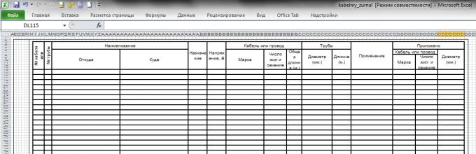
2. Drawing up and designing a cable log in Excel
There were people who were not happy with the exercises with printers and making collages. They went ahead and made the frame and title block in Excel.
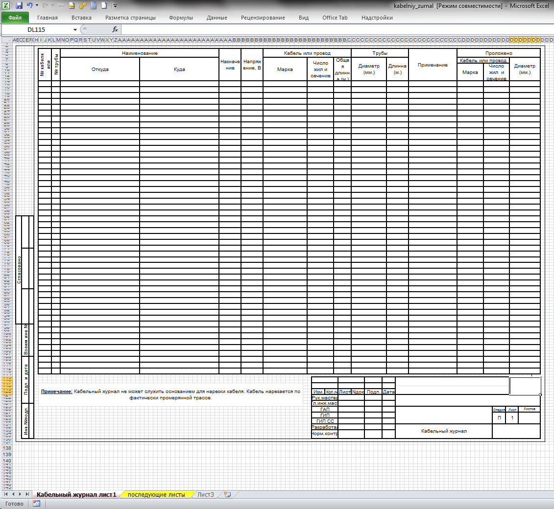
Separately the first sheet, separate subsequent sheets. The inconvenience of this method is that the table is broken, which means that using Excel functions causes certain difficulties, and filtering is generally impossible.
This method is still used today, and the screenshots show a fairly recent example from one of the Internet forums for designers. It is difficult to understand what GOST this magazine is based on. Apparently, the man himself came up with this form.
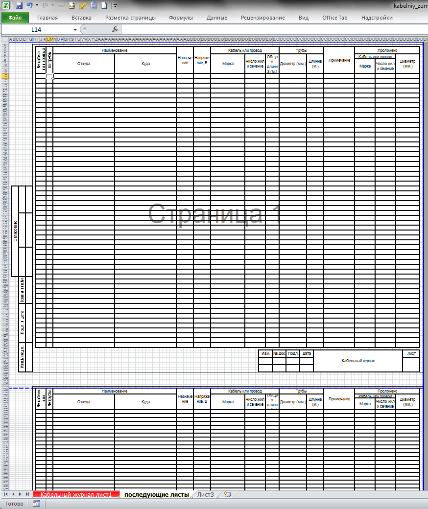
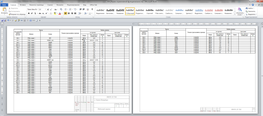
3. Compilation and design of a cable magazine in Word
The third way is to compile and design a cable magazine in Word. Working with tables in Word is not as convenient as in Excel, but the design is much easier to do. True, in order to make it convenient to work, you need to know and be able to use the “Header and Footer” tool, otherwise the design will “slide out”.
4. Drawing up and designing a cable magazine in AutoCAD
In fact, this method should be divided into two: before the appearance of tables in AutoCAD and after the appearance of tables. Before the advent of tables, this method was less convenient than in Word, because the table was a set of lines and text. And then everything depended on the skill and method of execution of the drawings by the designer:
- Drawing and design in Model space;
- Drawing and design in Sheet space;
- Drawing in Model space and design in Sheet space (one drawing - one sheet);
- item 2 or item 3, but all drawings are drawn up on one sheet.
The most convenient method is No. 3, because... allowed to make a continuous table in Model space, and then “cut” it into sheets using viewports.
With the advent of the “Table” element in AutoCAD, the fuss with lines and texts is gone, but otherwise, everything still depends on the way the drawings are made.
However, on one of the forums I saw a mention of another method. The designer made a line of the cable log as a block with attributes. And then he assembled a cable magazine from such blocks. He invented this method because... “switching lines in this case is much faster”.
5. Compiling a cable log in Excel and designing it in Word
This method combines the convenience of filling out a cable log in Excel and the convenience of formatting it in Word. The cable log is filled out in Excel and inserted into Word, in which the frame and main inscription (stamp) are made in the footers. Next, the width of the columns is adjusted and the cable magazine is ready for printing.
It would seem that the disadvantage of this method is the need to first delete the old table each time, and then insert and configure a new one. But it is not so. Word allows you to link a Word table and an Excel table. Thus, when you update data in Excel, the table in Word will also be updated.
6. Drawing up a cable log in Excel and design in AutoCAD
With the introduction of the Table element in AutoCAD and the ability to link it to Excel tables, this method is the best of the list.
Firstly, filling out a cable log table in Excel, in addition to convenience, provides additional benefits (see Tricks for creating a cable log in Excel).
Secondly, data from Excel is automatically updated in AutoCAD.
Thirdly, the AutoCAD table has the ability to automatically “split” into several fragments, which makes it possible to quickly and easily design a cable log in separate sheets (both using the table method in Model space, sheets in Sheet space, and using the table and design method in Model space). The interval between fragments, as well as the height of fragments, are set in the table properties.
Fourthly, when designing a cable log in Sheet space, the cable log can be included in the sheet binder, which provides additional advantages.
Make sure that you do not use anonymizers/proxies/VPN or other similar tools (TOR, Frigate, Zengate, etc..
Send a letter to abusesite if you are sure that this blocking is wrong.
In the letter, please include the following information about the blocking:
In addition, please clarify:
- What Internet provider do you use?
- What plugins are installed in your browser?
- Does the problem occur if you disable all plugins?
- Does the problem occur in another browser?
- Which software for organizing VPN/proxy/anonymization do you usually use? Does the problem occur if you disable them?
- How long has it been since you last checked your computer for viruses?
Your IP is blocked
Ensure that you do not use anonymizers/proxy/VPN or similar tools (TOR, Frigate, Zengate etc..
Contact abuse site if you make sure this block is a mistake.
Attach the following text in your email:
BLOCKED 5.189.204.11 Mozilla/5.0 (compatible; Googlebot/2.1; +http://www.google.com/bot.html)
Please specify also:
- What Internet provider (ISP) do you use?
- What plugins and addons are installed to your browser?
- Is it still blocking if you disable all plugins installed to your browser?
- Is it still blocking if you use another browser?
- What software do you often use for VPN/proxy/anonymization? Is it still blocking if you disable it?
- How long ago have you checked your computer for viruses?
Association "Roselectromontazh"
INSTRUCTIONS ABOUT COMPOSITION AND DESIGN
ELECTRICAL WORKING DOCUMENTATION
(GENERAL REQUIREMENTS AND RECOMMENDATIONS)
I1.16-10
MOSCOW 2010
Developed by: OJSC "NIPI TYAZHPROMELEKTROPROEKT"
Developers: Astrakhan V.D. (topic leader)
Komissarov A.A. (responsible executor)
Instead: M788-1073 (the document was issued to replace VSN 381-85)
ANNOTATION
This Instruction establishes the composition and rules for drawing up electrical working documentation (ED) individual projects for the construction, expansion, reconstruction and technical re-equipment of enterprises, buildings and structures for various purposes.
Requirements The Instructions are mandatory for all design organizations performing electric propulsion for the production of electrical equipment. installation work organizations of the Association "Roselektromontazh", unless other requirements are specified in the contract for the implementation of electric propulsion or in the technical specifications for the contract. In other cases of performing electric propulsion work, the materials in the Instructions are recommended.
The instructions take into account the requirements of the standard Russian Federation GOST R 21.1101-2009, extensive design experience of the Tyazhpromelektroproekt institutes, progressive technology for electrical installation work of organizations that are members of the Roselectromontazh Association.
The list of SPDS and ESKD standards, the requirements of which are taken into account in these Instructions, is given in the Appendix.
The Instructions use materials from work M788-1073 VNIPI Tyazhpromelektroproekt and VSN 381-85.
I approve
President of the Association
"Roselektromontazh"
E.F. Khomitsky
Date of introduction: 08/03/2010
1. GENERAL PROVISIONS
1) carrying out electrical installation work (hereinafter referred to as installation work);
2) production of electrical installation structures in workshops;
3) determining the need for electrical equipment, electrical products and materials;
4) determining the estimated cost of electrical equipment, materials and installation work.
1.2. In accordance with the prevailing construction design In practice, ERD includes working documentation of control and automation systems for engineering (shop) equipment, and in some cases, technological equipment (if the development of these systems is not part of the creation of the equipment and can be completed in one stage). In this regard, separate ERD documents, in addition to those specified in paragraph, are used when setting up and operating electrical equipment and installations.
1.6. Under a separate contract, documentation that is not included in the electronic work permit is performed:
1) working documentation for temporary power supply to electrical consumers for the construction period;
2) documentation transferred to manufacturing plants for the manufacture of low-voltage complete devices (cabinets, panels, boxes, posts, control panels, etc., hereinafter referred to as NKU);
3) design documentation for electrical equipment of a single (individual) production (previously called non-standardized equipment);
4) working documentation for the manufacture of individual structures of supporting and supporting devices for electrified transport and power lines;
5) design documentation for laying wires and cables on technological equipment;
6) design documentation for additional installation, replacement and removal of electrical equipment on complete electrical equipment;
7) standard design documentation of standard structures, products and assemblies (albums).
1.7. Making changes to the electronic document issued to the customer and binding standard projects and reused working drawings should be made in accordance with GOST R 21.1101-2009.
1.8. Electrical documentation is usually performed in an automated manner on paper and/or in the form of an electronic document.
When performing electronic documentation in the form of electronic documents and transferring documentation on electronic media, the requirements of GOST 2.051-2006 must be observed. Mutual correspondence between the electronic and paper forms is ensured by the developer.
The structure and composition of the details of electronic documents must ensure their circulation within software (display, modification, printing, recording and storage in databases, as well as transfer to other automated systems) while complying with regulatory requirements for document execution.
2. COMPOSITION OF ELECTRICAL WORKING DOCUMENTATION
2.1. The ERD transferred to the customer includes:
1) working drawings, combined into sets by type of work (hereinafter referred to as the main sets of working drawings);
2) documents attached to the main sets of working drawings.
2.2. The main set of working drawings includes:
2) drawings, diagrams, tables, etc.
2.3. The attached documents include:
1) reusable working documents (drawings, diagrams, tables, etc.);
2) sketch drawings of the general view of the NKU;
3) local estimate;
4) specification of equipment, products and materials;
5) questionnaires for electrical equipment (if necessary);
6) MEZ task (performed in necessary cases at the request of the installation organization);
7) other documents sent to the customer in accordance with the agreement (contract).
2.4. The main set of working drawings and attached documents without text documents are called “working drawings”.
The composition of the working drawings and individual explanations for their implementation are given in the appendix.
2.8. The main set of working drawings of any brand can be divided into several main sets according to any criteria (for example, by construction queues, building sections, technological units, etc.), assigning them the same brand and adding a serial number.
For example: EP1, EP2.
For each of these basic kits working documentation comply with the attached documents in full.
2.9. The main set of working drawings can be drawn up in separate documents, assigning them the brand of the main set and adding, through a dot, the serial number of the document indicated in Arabic numerals (for example, schematic diagrams EP1.1, plans for the location of electrical equipment and cable routing EP1.2).
The main set can be divided into the following documents:
Common data;
Electrical structural, functional and schematic diagrams;
Electrical connection diagrams; plans for the location of electrical equipment and the laying of electrical networks;
Drawings of installation of electrical equipment and structures for laying electrical networks;
Drawings of protective grounding of electrical installations;
Cable magazine;
Pipe procurement list;
Table for filling pipes with cables, etc.
The feasibility of dividing the main set of working drawings into documents is determined for a specific design. Drawings of several types can be combined into one document. For example, electrical and electrical layout plans can be combined with electrical and electrical installation drawings and a cable log.
2.10. The main set of working drawings can be combined with other main sets of working drawings for small volumes of documentation. The combined main set of working drawings is assigned one grade.
2.11. General data on working drawings.
2.11.1. The general data of the main set of working drawings for each brand includes:
1) a list of working drawings of the main set according to Form 1;
2) a list of reference and attached documents in Form 2;
3) a list of the main sets of working drawings in form 2;
4) general instructions;
5) symbols not established by national standards and the meanings of which are not indicated on other sheets of the main set of working drawings.
On the first sheet of general data of each main set of working drawings, in a rectangular frame, a record of the chief engineer of the project is placed, certifying the compliance of the electric propulsion equipment with current norms and regulations, and for buildings or structures with a fire hazardous and explosive nature of production, in addition, their safe operation in compliance with the measures provided for by the project .
2.11.2. When preparing the main set of working drawings as separate documents, the general data instead of the list of working drawings includes the “List of Documents of the Main Set”, and in each of the subsequent documents only the “List of Working Drawings” of the document is included.
If general data is included in one document together with part of the drawings of the main set, then the general data includes both the “List of documents of the main set” and the “List of working drawings” included in this document.
2.11.3. The list of reference and attached documents is compiled into sections:
1) reference documents;
2) attached documents.
The “Reference Documents” section includes drawings of typical structures, products and assemblies indicating the name of the series and release. The design organization does not issue reference documents.
2.11.4. The list of the main sets of working drawings is given on the general data sheets of the main set of the leading brand appointed by the general designer.
2.11.5. Examples of the execution of statements included in the general data of the main set of working drawings are shown in Fig. ... .
1) the basis for the development of working documentation;
2) a record of the results of testing for patentability and patent purity of equipment, devices, structures, materials and products used or developed for the first time in the project, as well as the numbers of patents, copyright certificates and applications for which decisions were made to issue patents, copyright certificates. Checks for patent purity of capital construction projects are carried out in accordance with the instructions of the general designers in accordance with current regulatory documents;
3) a list of types of work for which it is necessary to draw up inspection reports for hidden work;
4) other necessary instructions.
In general instructions, it is not allowed to repeat the technical requirements placed on other sheets of the main set of working drawings, and to describe the technical solutions adopted in the working drawings.
2.12. Attached documents.
2.12.1. Reused working documentation is linked to the construction conditions of the facility and is recorded in the “Attached Documents” section with the designation indicated in the binding stamp.
The rules for linking reusable working documentation are given in GOST R 21.1101-2009.
It is allowed to use working drawings of structures and parts made design organization and approved by its management for re-use, without a binding stamp, if no changes are made to the specified drawings. These working drawings are recorded in the list of attached documents without changing the designation.
2.12.2. The working documentation for the MEZ assignment includes:
1) list of electrical installation structures;
2) list of materials and products for the manufacture of electrical structures;
3) drawings of electrical installation structures (developed for the project being designed and reused);
4) pipe procurement list.
The following drawings should not be included in the MEZ assignment:
for the manufacture of cabinets with electrical equipment; for the installation of additional electrical equipment (relays, buttons, terminal blocks, etc.) and laying of wires on complete factory-made electrical equipment.
2.12.3. Sketch drawings of the general view of the NKU are drawn up for non-standard complete devices.
It is allowed, instead of sketch drawings of the general view of the NKU, to include in the electronic design documentation general views of the NKU, developed as part of the documentation transferred to the manufacturers of the NKU, without changing the designation of the drawing (without a reference stamp).
2.12.4. Local estimates are drawn up in accordance with current Methodological recommendations to determine the estimated cost and contract prices in construction and major repairs on the territory of the Russian Federation.
2.12.5. The specification of equipment, products and materials is carried out in accordance with the requirements of GOST 21.110-95.
2.12.6. Questionnaires for electrical equipment are made up of:
1) standard complete devices (KTP, switchgear, KSO);
2) power transformers of size IV and larger;
3) thyristor converter devices;
4) distribution panels, resistor blocks, excitation regulators and other electrical equipment, if provided for in the ordering procedure.
Forms of questionnaires are used in agreement with the equipment manufacturer.
3. DESIGNATION OF ERD
3.1. The main sets of working drawings, documents of the main sets (when the main sets are prepared as separate documents), drawings and text documents attached to the main sets are assigned independent designations.
3.2. The designation of the main set of working drawings includes the base designation and, separated by a hyphen, the mark of the main set.
Examples: XXXX - XX - ETH,
XXXX - XX - EP1,
XXXX - XX - EP2,
where: ХХХХ - agreement (contract) number or digital code of the object;
XX - number of the building or structure according to the general plan (if necessary);
XXXX - XX - basic designation;
ETH, EP1, EP2 - brands of the main sets of working drawings.
3.3. When preparing the main set of working drawings as separate documents, the designation of each document is made up of the designation of the main set of working drawings with the addition of the document serial number through a dot.
Examples: XXXX - XX - EP1.1,
XXXX - XX - EP1.2.
3.4. Designations for general sketch drawings of the ASSEMBLY include the designation of the main set of working drawings with the addition of alphanumeric indices through a dot, consisting of the capital letter “H” and serial numbers of the drawings.
Examples: XXXX - XX - EP1.H1,
XXXX - XX - EP1.N2.
3.5. Designations of structural drawings and pipe procurement sheets of working documentation for the MEZ task, developed for the designed facility, include the designation of the main set of working drawings with the addition of alphanumeric indices through a dot, consisting of the capital letter “I” and serial numbers of the drawings.
Examples: XXXX - XX - EP1.I1,
XXXX - XX - EP1.I2.
In the designation of the assembly drawing of the design of the working documentation of the MEZ task, additionally at the end of the designation a letter index from capital letters"SB".
Example: XXXX - XX - EP1.I3SB.
The designations of the list of electrical installation structures and the list of materials and products for the manufacture of electrical installation structures included in the working documentation of the MEZ task include the designation of the main set of working drawings with the addition of alphanumeric indices through a dot, consisting respectively of the capital letters “IVK” and “IVM” and ordinal statement numbers.
Examples: XXXX - XX - EP1.IVK1,
XXXX - XX - EP1.IVK2,
XXXX - XX - EP1.IVM1,
XXXX - XX - EP1.IVM2.
3.6. The designation of text documents included in the attached documents to the main set of working drawings includes the designation of the main set of working drawings with the addition of a letter index of capital letters through a dot.
Letter indices are used:
LS - for local estimates;
C - for specification of equipment, products and materials;
OL - for the questionnaire.
Examples: XXXX - XX - EP.LS,
XXXX - XX - EP.S.
If the attached documents contain several text documents of the same type, the serial number of the document is added to the letter index.
Examples: XXXX - XX - EP1.S1,
XXXX - XX - EP1.C2.
3.7. Working drawings developed as reuse drawings are given a non-object designation.
4. GENERAL RULES FOR REGISTRATION OF ERD
4.1. Each sheet of the working drawing and text document must have a main inscription and additional columns in accordance with GOST R 21.1101-2009 (see figure). Exceptions may include documents prepared using universal PC programs (for example, estimates). On these documents, only designations are applied to the free spaces of the sheets, preferably in the lower right corner.
The main inscription according to Form 3 GOST R 21.1101-2009 is used:
1) for all sheets of the main set of working drawings, with the exception of subsequent sheets of the cable (cable-tube) magazine;
2) for the first sheet of specifications of equipment, products and materials in the case when the title page is not fulfilled (see paragraph);
3) for the first sheets of the list of electrical installation structures, the list of materials and products for the manufacture of electrical installation structures, the pipe procurement list, as well as sheets of drawings of electrical installation structures developed for the facility being designed;
4) for general sketch drawings of the NKU.
An example of filling out the main inscription according to form 3, see Fig. .
The main inscription according to Form 5 GOST R 21.1101-2009 is used for sheets of drawings of electrical installation structures developed as re-use drawings, and for the first sheets of text documents drawn up with title pages (see fig.).
The main inscription in accordance with Form 6 GOST R 21.1101-2009 is used for subsequent sheets of attached text documents, as well as subsequent sheets of cable (cable-pipe) logs (see Fig.).
Additional columns are applied to the sheet filing field and filled in depending on the procedure for approval and storage of documentation adopted in the design organization.
4.2. The nature of the work performed (developed, checked, standard control), the positions of the persons responsible for issuing the documentation (chief specialist or head of department, chief engineer of the project), their names and signatures are indicated in the corresponding columns of the title block and are written in it from top to bottom, starting with the developer (see pictures,).
4.3. In the title block:
1) the column “Sheet” on documents consisting of one sheet is not filled out. In this case, fill out only the “Sheets” column;
2) the column “Sheets” is filled out only on the first sheet;
3) on the first sheet of a text document for double-sided printing, in the “Sheets” column, indicate the total number of pages;
4) all sheets of the main sets of working drawings, documents of the main sets (when the main sets are prepared as separate documents), as well as drawings and text documents are numbered in order, starting with one.
For an example of filling out the title page, see Fig. .
If the volume is small, it is permissible to omit the title page. In this case, on the first sheet of the specification of equipment, products and materials, the main inscription is made according to Form 3 GOST R 21.1101-2009 with the signature of the GUI.
4.5. The chief engineer of the project signs:
1) the first sheet of general data;
2) title pages of working documents;
3) assignment to related design organizations (divisions).
5. RULES FOR EXECUTION OF WORKING DRAWINGS
5.1. Basic connection diagrams are carried out in accordance with GOST 2.702-75*. Each element and (or) device shown on the circuit diagram and connection diagram must have an alphanumeric designation in accordance with the requirements of GOST 2.710-81*. Instead of connection diagrams, it is allowed to create connection tables.
In the list of elements for the circuit diagram, the names of the elements should be written in accordance with the requirements of regulatory documents; at the same time, it is allowed not to write down the designations of state standards, technical conditions, etc., on the basis of which these elements are applied.
5.2. Plans for the location of electrical equipment, laying electrical networks and grounding networks (hereinafter referred to as location plans).
5.2.1. Layout plans for buildings and structures are carried out on sub-bases, which serve as plans for buildings and structures. Location plans outside buildings and structures are made on sub-bases, which are layout plans or geo-bases. Recommended scales of images on the plans are indicated in the appendix.
5.2.2. The following is shown on the plans for the location of buildings and structures:
1) coordination axes of a building or structure and the distances between them;
2) marks of finished floors of floors and main areas;
3) building and technological structures - in the form of contour outlines;
4) technological and engineering equipment - in the form of simplified contour outlines;
5) boundaries and classes of explosive and fire hazardous areas, categories and groups of explosive mixtures according to the classification of Electrical Installation Rules;
6) name of departments, sections of workshops, premises, etc.;
7) names or designations of electrical rooms, cable tunnels and other electrical structures;
8) electrical equipment, electrical networks and grounding networks;
9) connection of electrical equipment, electrical networks and grounding networks;
10) locations of fittings and other separation seals;
11) sections of cable routes indicating the location of cables on the shelves for single-layer cable laying.
5.2.3. The contours of buildings, structures, elements of building and technological structures are shown as solid outlines on the layout plans thin lines according to GOST 2.303-68*.
5.2.4. Electrical equipment and electrical wiring in buildings and structures are applied to the layout plans with conventional graphic images in accordance with GOST 21.614-88*. The dimensions of the images of cabinets, panels, consoles, boxes, electrical devices and electrical equipment of open switchgears should be taken according to their actual dimensions on the scale of the drawing.
Electrical wiring outside buildings and structures is applied to the layout plans with conventional graphic images and designated in accordance with GOST 21.204-93, section 7 “Conventional graphic symbols of utility networks.”
Designations of electrical rooms, electrical equipment and cable wiring (with the exception of wiring outside buildings and structures) are recommended to be carried out in accordance with the work of VNIPI Tyazhpromelektroproekt “Guidelines for alphanumeric designations in electrical design and design documentation” (RTM 36.18.32.3 -93).
5.2.5. Electrical equipment layout plans, as a rule, are combined with plans for laying electrical networks and protective grounding networks. If necessary, provide sections, non-standard components for installing electrical equipment and laying electrical networks, layout diagrams of busbars, as well as installation openings, exits, roads for transporting large-sized electrical equipment.
5.2.6. Electrical equipment (with the exception of electrical receivers, complete devices, devices installed directly on technological equipment) and electrical network routes must have references and marks on the plan. It is allowed not to indicate the binding of single devices (for example, starters, buttons, etc.) and openly laid cables, if the places of their installation or laying are clear without binding.
5.2.7. The connection of electrical equipment and electrical networks is carried out, as a rule, to the coordination axes of buildings and structures or to the axes of technological equipment, provided that this equipment is installed before laying the electrical wiring pipes, and its axes are linked to the construction axes.
When laying electrical networks hidden in pipes (in floors, in the ground, in foundations), the ends of the pipes are tied and the laying and exit marks are indicated. In the foundations of complex equipment, additional connections are made between the ends of the pipes and the nearest foundation bolts.
When laying open electrical networks along technological installations, structures and building structures (galleries, trusses, columns), electrical networks are connected to the specified installations, structures and structures.
5.2.8. On the layout plans of electrical equipment (with the exception of electrical equipment installed on technological equipment by mechanical installation organizations and (or) supplied assembled with mechanisms), structures and products, item numbers are indicated in accordance with the specification and they are marked on the leader line shelf. For electrical equipment under the shelf, leader lines are marked with alphanumeric designations according to the basic control diagrams (tables of electric drives).
For example:
Cable wiring and pipe gaskets are marked with alphanumeric designations according to cable and (or) cable and pipe logs, and for pipes the diameter is also marked according to the standard.
5.2.9. The layout plans contain specifications of electrical equipment, products, structures, parts and materials necessary for installation work according to these drawings in Form 7 GOST R 21.1101-2009. When making drawings using the group method (for example, for a group of technological lines), group specifications are drawn up in Form 8 GOST R 21.1101-2009.
5.2.10. The specification on the drawing is placed above the main inscription, usually in the upper corner. If the drawing is made on an A4 sheet, the specification is placed below the graphic image.
The specification may be placed on separate sheets. In this case, the name of this specification is given in the main inscription.
5.2.11. The specification is compiled into sections in the following sequence:
1) electrical equipment (except for electrical equipment installed on technological equipment by mechanical installation organizations and (or) supplied assembled with mechanisms);
2) electrical installation products;
3) designs;
4) details (according to drawing, without drawing);
5) standard products;
6) materials.
If the total number of positions is up to 20, the names of sections may not be indicated. Reserve lines are left between sections.
5.2.12. Electrical equipment is recorded within the first section of the specification by groups of elements of the same name (in ascending order of types, parameters, numbers included in their designation) in the following sequence:
1) electrical equipment, for the manufacture of which questionnaires and tasks are issued to manufacturing plants;
2) serial electrical equipment.
5.2.13. Materials in the specification are written in the following sequence:
1) ferrous metals (including pipes);
2) non-ferrous metals;
3) insulating materials.
5.2.14. The specification columns indicate:
1) in the column “Pos.” - serial number of positions indicated on the images;
2) in the “Designation” column - designation of the corresponding working drawings of structures and parts both manufactured in the MEZ and in the installation area.
3) in the column “Name” - short name according to the catalog (for electrical equipment), name according to the product range, name of structures and parts indicated in the title block of the corresponding working drawing.
For parts manufactured without a drawing, standard products and materials, write down the name and symbol specified in the relevant standards. After the name, the type is indicated in the column and brief characteristics are given;
4) in the column “Quantity.” - quantity (pieces) in the drawing.
For materials specified in meters, an additional letter “m” is entered in the column;
5) in the column “Unit weight, kg” - the weight of the unit, part (without drawing), material;
6) in the “Note” column - additional information related to the elements recorded in the specification. For example, it is allowed to indicate the total weight in kg.
5.2.15. The consumption of materials in the specifications should be recorded with the accuracy specified in the application table.
5.3. Cable magazines.
5.3.1. Depending on the adopted type and method of laying cables, a cable log for laying cables using the route method, a cable and pipe log, or a cable log are made.
5.3.2. In the cable log for laying the routes using the route method, a column is provided “Section of the cable route, wires”. This column indicates the designations and numbers of cable routes and pipes according to the layout plan, as well as the numbers of shelves of cable structures, pipes, trays, boxes along the entire length of the route.
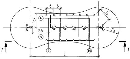
An example of a cable magazine for laying cables using the route method is shown in Fig. . The shape of the cable log corresponds to Form 7 GOST 21.613-88*.
When completing the work documentation task for the MEZ of the pipe procurement list in the cable and pipe log, the columns “Diameter according to standard” and “Length” related to pipes are not filled in.
An example of a cable and pipe log is shown in Fig. . The form of the cable and pipe magazine corresponds to Form 6 GOST 21.613-88*.
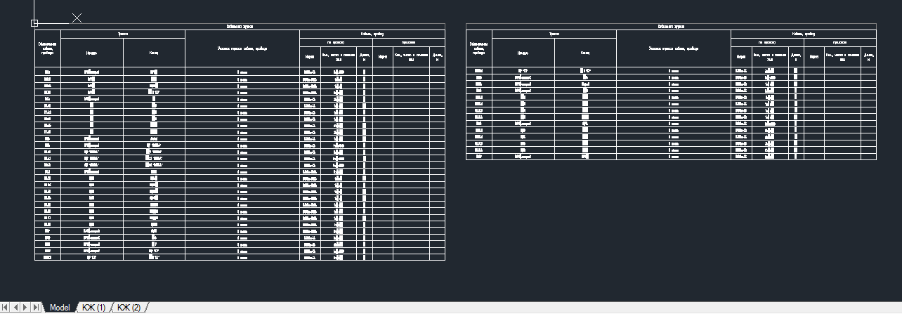
An example of a cable log is shown in Fig. . The shape of the cable magazine corresponds to Form 6 GOST 21.608-84.
5.3.3. Power and control cables in a cable magazine are usually grouped by drive, type of current, voltage, etc. and are written in ascending order of numbers or letter codes.
When cables approach control panels, in the “Start” and “End” columns indicate the designation of the control panel and the number of the panel to which the cable is connected.
The length of cables, wires, pipes in the “Length” columns in the cable and cable and pipe logs is recorded taking into account the allowance for bends, turns and waste with the accuracy specified in the appendix.
A cable log is not performed if the route and all information about the cables (beginning, end, brand, cross-section and length) are available on the circuit diagram of the supply or distribution network.
5.3.4. On the last page of the cable log there is a table of the need for cables and wires, and in the cable and pipe log, in addition, a table of the need for pipes is given.
When performing a pipe procurement list in the MEZ task, the table of pipe requirements is not given in the cable and pipe log, but is given in the pipe procurement sheet. The forms of cable and pipe demand tables correspond to forms 4 and 5 of GOST 21.613-88*.
Examples of cable and pipe requirements tables are shown in Fig. 1, respectively. and rice .
5.4. When laying two or more cables in pipes, a list of filling the pipes with cables should be drawn up. In the “Pipe” column indicate the designation of the pipe and, separated by a hyphen, the diameter of the pipe; the form of the list of filling pipes with cables corresponds to Form 9 GOST 21.613-88*.
5.5. Sketch drawings of the general view of non-standard low-voltage complete devices (LVDs) must contain an image of the structure - front view, top view, number and order of panels, dimensions, text instructions and inscriptions necessary for general idea about the device.
An example of a general outline drawing of an NKU is shown in Fig. .
5.6. Working documentation for the MEZ task.
5.6.1. Drawings of electrical installation structures intended for manufacturing in the MEZ are carried out in cases where there are no corresponding factory-made products, standard drawings of electrical installation structures and drawings of electrical installation structures for reuse.
Drawings of electrical installation structures are usually made on a scale of 1:5, 1:10 or 1:20.
On the drawings of electrical installation structures, a specification for one structure or a group specification for several designs is placed in accordance with forms 7 and 8 GOST R 21.1101-2009.
Examples of specification and group specification implementation are shown in Fig. and rice .
5.6.2. All electrical installation structures to be manufactured at the MEZ according to standard drawings, re-use drawings and newly developed drawings are included in the list of electrical installation structures.
The form of the statement corresponds to Form 10 GOST 21.613-88*.
An example of the statement is shown in Fig. .
5.6.3. All materials and products necessary for the manufacture of electrical structures in the MEZ are included in the list of materials and products.
An example of the statement is shown in Fig. .
5.7. Pipe procurement list.
5.7.1. The pipe procurement list is intended for the procurement of pipe elements in the oil extraction plant. A pipe procurement list is compiled for both metal pipes and plastic (polyethylene, polyvinyl chloride) pipes.
5.7.2. The pipe procurement list is carried out in the following cases:
1) for electrical networks, where the laying of cables and wires in pipes predominates and where the volume of pipe laying determines the feasibility of procuring pipe elements in the MEZ;
2) for electrical networks laid in pipes in the foundations of complex equipment.
5.7.3. When filling out the pipe procurement list, in the column “Pipe route section” indicate:
1) the length of the pipe sections between the vertices of the corners in meters;
2) values of angles in degrees and bending radii in millimeters;
3) designations of broaching boxes and pipe blocks;
When manufacturing a pipe from normalized elements, in the column “Pipe route section” indicate:
1) the length of normalized straight sections of pipes, and, if necessary, the length of the additional section in meters;
2) types of connecting angles indicating the bending angle in degrees;
3) designation of broaching boxes and pipe blocks;
4) designation of the drawing, which shows the continuation of the pipe.
In the “Note” column, if necessary, provide a sketch of the pipe, as well as other additional information.
5.7.5. On the last sheet of the pipe procurement list, a table of pipe requirements is given (see Fig.).
5.7.6. When using only metal pipes for electrical networks, the pipe procurement list is performed according to Form 8 GOST 21.613-88*. When using both metal and plastic pipes, the pipe procurement list is made in the form shown in Fig. .
6.1. Copies of working documentation documents for transfer to the customer are completed in folders sheet by sheet, folded in A4 format, as a rule, according to the main sets of working drawings.
It is allowed to bind* copies of working documents into volumes folded in A4 format.
*Note - Under stitching understood accommodation materials working documentation V bindings or V solid folders With easily removable fastenings (locks).
The number of sheets included in a folder (volume) is determined from the need to ensure ease of use, but not more than 300 sheets of A4 format or an equivalent number of sheets of other formats.
6.2. Each document, volume, as well as the folder with the documents placed in it is decorated with a cover. The cover is not numbered and is not included in the total number of sheets.
6.3. The first sheet of a bound document, a volume consisting of several documents, or a folder with working documentation is the title page. The title page is made according to form 12 GOST R 21.1101-2009.
Examples of making title pages are shown in figures and.
6.4. All sheets of the bound volume are numbered through sheet numbering, starting with the title page. In this case, the title page is not numbered. The sheet number on sheets of text and graphic documents is indicated in the upper right corner of the working field of the sheet. This requirement is mandatory only for electronic documentation subject to state examination.
In addition, text and graphic documents included in the volume and having an independent designation must have serial numbering of sheets in the title block within the document with one designation.
6.5. When collecting several documents in the form of a volume or folder, after the title page the contents of the volume (folder) are given, which is a list of documents included in the volume (folder).
Documents in the contents are recorded in the sequence in which they are compiled into a volume (folder). The cover and title page are not included in the contents.
The first sheet of contents of the volume (folder) is drawn up with the main inscription according to Form 5 GOST R 21.1101-2009, the subsequent ones - according to Form 6 GOST R 21.1101-2009.
Example- XXXX- XX- EPS.
In the title block in the document name column, indicate “Volume Contents” or, respectively, “Folder Contents”.
ANNEX 1
SPDS STANDARDS
|
Standard control of design and working documentation |
|
|
Basic requirements for design and working documentation |
|
|
Legend pipelines |
|
|
Conventional graphic symbols and images of elements master plans and transport structures |
|
|
Rules for fulfilling the specifications of equipment, products and materials |
|
|
Lifting and transport equipment. Conditional images |
|
|
Accuracy Characteristic Designations |
|
|
Rules for the execution of architectural and construction working drawings |
|
|
Accounting and storage project documentation |
|
|
Conditional graphic designations in schemes. Energy equipment |
|
|
Automation of technological processes. Symbols of devices and automation equipment in diagrams |
|
|
Rules for the execution of working documentation for wired communications |
|
|
Internal electric lighting. Working drawings |
|
|
Centralized energy saving management. Conventional graphic and letter designations of the type and content of information |
|
|
Power equipment. Working drawings |
|
|
Conditional graphic images of electrical equipment and wiring on plans |
|
|
Requirements for the preparation of design documentation for construction abroad |
ESKD STANDARDS
|
Electronic documents. General provisions |
|
|
General requirements to text documents |
|
|
Text documents |
|
|
Basic requirements for drawings |
|
|
Group and basic design documents |
|
|
Drawing fonts |
|
|
Images - views, sections, sections |
|
|
Designations of graphic materials and rules for their application in drawings |
|
|
Drawing dimensions and maximum deviations |
|
|
Indication on the drawings of tolerances of the shape and location of surfaces |
|
|
Conventional images and designations of permanent connections |
|
|
Instructions on the drawings for marking and branding of products |
|
|
Rules for writing inscriptions technical requirements and tables on graphic documents |
|
|
Letter designations |
|
|
Rules for making drawings of metal structures |
|
|
Scheme. Types and types. General requirements for implementation |
|
|
Rules for executing electrical circuits |
|
|
Rules for executing digital electrical circuits computer technology |
|
|
Conventional designations of wires and contact connections of electrical elements, equipment and sections of circuits in electrical circuits |
|
|
Alphanumeric designations in electrical circuits |
|
|
Conditional graphic designations in schemes. Designations general use |
|
|
Patent Form |
Note. ESKD standards are applied taking into account the requirements of SPDS standards.
APPENDIX 2
1. Construction specifications (drawings and text instructions) contain requirements for construction solutions. As a rule, construction assignments for premises also include requirements for the implementation of ventilation, plumbing, fire safety and other devices for these premises and structures.
2. The construction task is carried out on a part of the building (structure), corresponding to one or more main sets of working drawings, or on the building (structure) as a whole, corresponding to all electrical working documentation.
3. The construction task is issued for the installation of electrical premises, including means for transporting large-sized electrical equipment (trolleys, hoists, single-beam overhead cranes, overhead cranes), foundations for electrical equipment, embedded parts, holes, niches, lightning protection devices, etc.
4. Construction assignments must contain the data necessary for the development of construction working drawings, such as: room dimensions, hole diameters, dimensions of openings, niches, loads on building elements from electrical equipment and electrical network structures, etc.
5. It is allowed to issue an additional construction task for embedded parts, openings, holes (with a diameter of more than 30 mm), which were revealed after the completion of electrical working drawings.
6. Construction working drawings containing solutions to the requirements of the construction task are subject to agreement with the developer of the construction task.
7. Construction tasks and additional construction tasks are sent to the chief engineer of the project for the facility for implementation by the relevant design organizations (divisions). Construction assignments may also be sent to the electrical installation organization upon request.
On copies of construction assignments submitted to the electrical installation organization at its request, the following should be written:
“The drawings do not reflect changes made during the development of the construction drawings.”
APPENDIX 3
Mandatory
|
Name of the main set of working drawings |
Note |
||
|
Electricity supply |
|||
|
Electricity supply. Substations |
ep |
||
|
Overhead power lines |
ev |
||
|
Cable power lines |
ek |
||
|
Electrochemical protection |
ehz |
Not covered in the Instructions. Developed by specialized organizations |
|
|
Lightning protection and grounding |
eg |
||
|
Traction networks for electrified industrial railway transport |
this |
||
|
Power equipment |
Em |
||
|
Automated process control systems (APCS) |
eth |
Only in terms of equipment management |
|
|
Internal electric lighting |
|||
|
Electric lighting of the territories of industrial enterprises. Working drawings |
|||
|
Energy supply and engineering equipment management systems |
APPENDIX 4
1. ELECTRIC SUPPLY. SUBSTATIONS - EP
1.1. This section determines the composition of the working drawings of an electrical substation or distribution point 6 ... 500 kV.
1.2. Working drawings include:
1) general data on working drawings;
2) schematic diagram of the main circuits;
3) basic (complete) diagrams of relay protection, control, measurement, signaling, etc.;
4) plans for the location of electrical equipment, busbars and laying of grounding networks;
5) plans for laying electrical networks;
6) connection diagrams (tables);
7) cable magazine;
8) working documentation for the MEZ task;
9) sketch drawings of the general view of the NKU.
1.3. In addition to what is listed in paragraph, general instructions include:
1) information about clarification of the project;
2) table of settings for protection relays and automation of lines 6 ... 500 kV.
1.4. The diagram of the main circuits is performed in a single-line image.
The diagram indicates:
1) rated voltage of busbars,
2) types, rated currents and resistance of resistors (if they are present in the circuit);
3) winding connection diagrams, type, rated power and voltage of power transformers;
4) winding connection diagrams, type and rated voltage of voltage transformers;
5) type and rated currents of current transformers;
6) types of relay protection, automation and measuring instruments;
7) brands, cross-sections and number of conductors of supply and outgoing lines.
1.5. Schematic (complete) diagrams of relay protection, control, measurement, alarm, automatic transfer switch, etc. are presented in full in a multi-linear image indicating all elements of complete devices.
Electronic elements, microprocessor devices, etc., which have their own electrical circuits, are depicted on circuit diagrams in the form of rectangles or other conventional graphic images. If necessary, these electrical diagrams can be included in the main set of working drawings. In cases where the electrical diagrams of the specified elements and devices are made as re-use drawings and have their own designations, they are placed in the documents attached to the main set of working drawings.
1.6. The cable log takes into account all the cables of the electrical substation (distribution point), including outgoing ones, and the specifications of equipment, products and materials - only cables related to the internal connections of the electrical substation (distribution point).
1) technological mechanisms and assemblies are supplied complete with electrical drive equipment, automation systems, and electrical working documentation for construction - working drawings, as well as text documents of electric power plants are not developed;
2) technological mechanisms and assemblies are supplied for construction complete with electrical drive equipment, automation systems, but without electrical engineering working documentation for construction - working drawings for electrical installation work and text documents of electronic electric drives are developed;
3) technological mechanisms and units are supplied not fully equipped with electrical equipment of drives and (or) automation systems and without electrical working documentation for construction - working drawings for electrical installation work and text documents of electric propulsion systems are being developed, as well as working documentation for automation systems.
Note. It is meant that in all three options, technological mechanisms and assemblies contain remote electrical equipment for drives and (or) remote automation equipment.
6.4. The layout diagram of control stations and electrical equipment shows:
1) the location of electric drives, hydraulic drives and pneumatic drives involved in the technological process and controlled by operators - technologists;
2) the location of control posts and workstations, indicating by arrows or in tables from which post (workstation) which drives are controlled.
8.1. Working drawings include:
1) general data on working drawings;
2) electrical schematic diagrams of complete transformer substations (CTS) of supply and distribution networks;
3) schematic diagrams of electric drive control;
4) connection diagrams (tables);
5) plans for the location of electrical equipment and the laying of electrical networks;
6) cable and pipe (cable) magazine;
7) pipe procurement list;
8) list of filling pipes with cables and wires;
9) working documentation for the MEZ task;
10) dimensional drawings of the NKU.
8.2. Location of electrical equipment, laying of busbars, wires and cables, grounding devices, etc. may be shown both on separate drawings and on one, if this does not make it difficult to read.
An example of the implementation of the plan for laying trolley lines (fragment) is shown in Fig. .
An example of a plan (fragment) and a section for laying a main busbar is shown in Fig. .
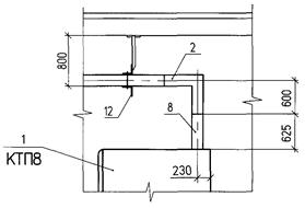
An example of the implementation of the 2KTP location plan is shown in Fig. .
An example of the plan and section for laying distribution busbars is shown in Fig. , .
Note. Definition of the term “power electrical equipment”.
Power electrical equipment includes:
Complete transformer substations 6, 10/0.4, 0.66 kV;
Electrical networks for powering electrical receivers with voltage up to 1 kV within the designed building or structure;
Control devices for electric drives up to 1 kV of ventilation and air conditioning systems, water supply, sewerage and other general-purpose mechanisms, if the electric drives of these systems and mechanisms are supplied without them.
9. INTERNAL ELECTRIC LIGHTING - EO
9.1. Working drawings include:
1) general data on working drawings;
2) plans for the location of electrical equipment and the laying of electrical networks;
3) schematic diagrams of the supply network;
4) schematic diagrams of remote lighting control;
5) connection diagrams for complete switchgears for voltages up to 1000 V;
6) cable and pipe log (if necessary);
7) drawings of installation of electrical equipment (in the absence of standard ones);
8) drawings of structures and parts intended for installation of electrical equipment (in the absence of standard ones).
10. ELECTRIC LIGHTING OF THE TERRITORY OF INDUSTRIAL ENTERPRISES AND PUBLIC BUILDINGS AND STRUCTURES - EN
10.1. Working drawings include:
1) general data on working drawings;
2) area lighting plan;
3) a list of supports and floodlight masts with lighting fixtures and electrical equipment installed on them;
4) power supply and lighting control circuits for the territory;
5) drawings of non-standard installation units for lighting fixtures and electrical equipment;
6) sketch drawings of general types of non-standard structures intended for the installation of lighting fixtures and electrical equipment.
APPENDIX 5
|
Image name |
|
|
Location of electrical installations and power lines with voltages above 1 kV |
1:10000; 1:20000 |
|
RP 6 - 10 kV and transformer substations 6 - 10/0.4 kV |
|
|
Routes of external cable networks |
|
|
Location of electrical equipment and cable routing |
|
|
Laying pipes, tires |
1:20; 1:25; 1:50 |
|
Electrical installation structures |
|
|
Traction networks for electrified industrial railway transport: |
|
|
1) location of overhead, rail, cable lines and contact networks |
1:500; 1:1000; 1:2000 |
|
2) installation of supports, structures, apparatus |
1:20; 1:25; 1:50; 1:100 |
Appendix 6
|
Name |
Degree of accuracy |
|
1. Rolled ferrous and non-ferrous metals in the specification on the drawing: |
|
|
With a part weight up to 1 kg |
|
|
When the part weight is more than 1 kg |
|
|
2. Rolled ferrous metals: |
|
|
3. Rolled non-ferrous metals: |
|
|
In the list of materials and products, the tasks of the MEZ |
|
|
In the specifications of equipment, products and materials |
|
|
4. Steel pipes: |
|
|
In the specification on the drawing |
|
|
In the pipe procurement list |
|
|
Pipe needs table |
|
|
In the list of materials and products, the tasks of the MEZ |
0.001 km |
|
In the specifications of equipment, products and materials |
0.001 km |
|
5. Cables and wires: |
|
|
In the cable magazine for cable lengths up to 10 m |
|
|
In the cable log for cable lengths over 10 m |
|
|
The table requires cables and wires |
|
|
In the specifications of equipment, products and materials |
SHEET
WORKING DRAWINGS OF THE MAIN SET
Rice. 2. An example of a list of working drawings for the main set
SHEET
REFERENCE AND ATTACHED DOCUMENTS
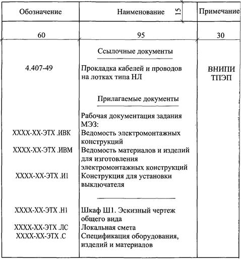
Rice. 3. An example of a list of referenced and attached documents
SHEET
BASIC SETS OF WORKING DRAWINGS
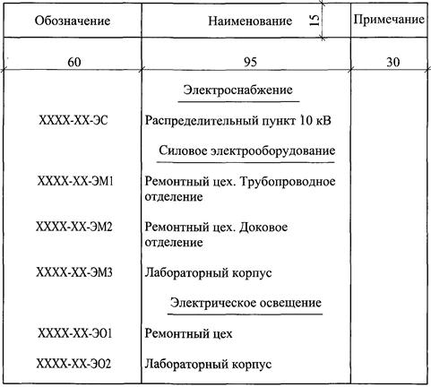
Rice. 4. An example of a list of main sets of working drawings
SHEET
DOCUMENTS OF THE MAIN SET OF WORKING DRAWINGS
Rice. 5. An example of a list of documents for the main set of working drawings
Note- The size in brackets is for the bottom frame of A4 and A3 sheets.
Rice. 6. Location of the main inscription, additional columns to it and dimensional frames on the sheets
Rice. 7. An example of filling out the main inscription according to Form 3 GOST R 21.1101-2009
Rice. 8. An example of filling out the main inscription according to Form 5 GOST R 21.1101-2009
Rice. 9. An example of filling out the main inscription according to Form 6 GOST R 21.1101-2009
Rice. 10. Example of specification execution on the layout plan
Note
Rice. 11. An example of a group specification on a layout plan
Rice. 12. An example of a cable magazine for laying cables using the route method
Rice. 13. An example of a cable and pipe magazine
Rice. 14. Example of a cable log
NEED FOR CABLES AND WIRES
Rice. 15. An example of a table of cable and wire requirements
NEED FOR PIPES
Rice. 16. Example of a pipe demand table
Rice. 17. An example of a list of filling pipes with cables
Rice. 18. An example of a general outline drawing of an NKU
Rice. 19. An example of specification implementation on a design drawing for an MEZ task
Note. Number column "Count." not standardized.
Rice. 20. An example of the implementation of a group specification on a design drawing for an MEZ task
Rice. 21. An example of completing an electrical installation list
structures to be manufactured at the MEZ (IVK)
Rice. 22. Example of making a list of materials and products
for the manufacture of electrical wiring
structures in MEZ (IVM)
Rice. 23. An example of a pipe procurement list
Rice. 24. An example of the design of a title page for a folder (volume),
which includes the electric propulsion engine of block B of the EM1 brand as a whole
Rice. 25. Example of a title page for an equipment specification,
products and materials
Rice. 26. Example of performing the contents of a volume (folder)
Rice. 27. An example of the implementation of the layout plan for switchgear cabinets,
busbars and laying of the grounding network in the electrical room
Rice. 28. Example of a cable route layout plan
Plan
Rice. 29. An example of the lightning protection installation diagram
devices and external grounding devices
Traction substation No. 2
Rice. 30. An example of the implementation of a plan for a contact network, supply and suction lines
electrified industrial railway transport
|
Pos. Designation |
Name |
Note |
|
|
At the mechanism |
|||
|
No. 18 - M |
Motors AIR90L4, 380 V, 50 Hz |
||
|
1395 min, 100% duty cycle |
|||
|
Local control post |
|||
|
PKU15-21-12154U2, TU 16-526.333-83 |
|||
|
No. 1-KE011, isp. 4 “Start”, black. |
|||
|
No. 2-KE031, isp. 5 “Stop”, red. |
|||
|
QF1, KK1, KM1 |
Block B5130-2V74GUHL4 |
||
|
Switch UP5311-S23U3 |
|||
|
Remote control post |
|||
|
Push-button switch, KE011U3 |
|||
|
Spanish 4 “Start”, black. |
|||
|
Push-button switch, KE031U3 |
|||
|
Spanish 54 "Stop", red. |
|||
|
Signal fittings AS12011U2 |
The scheme provides for the management of:
Local, buttons SB1, SB3
Remote from the control station, buttons SB4, SB2
Rice. 31. An example of a circuit diagram for controlling an electric drive
Rice. 32. Example of a connection diagram
|
Complete device (type, designation, document) |
Panel AC1, panel 4 |
|||||||
|
Cable designation |
Where to connect |
Cable core marking (general) |
Additional data |
Cable direction |
Cable brand |
Note |
||
|
Designation of terminal block (device) |
Clamp no. |
Marking on the clamp |
||||||
|
No. 18 - AX1 |
kvvg 1(5´ 2.5) |
|||||||
|
No. 18 - UV |
vvg 1(3´ 2.5) |
|||||||
|
bridge |
1´ 1.5 |
|||||||
Rice. 33. Example of execution of the connection table
Rice. 34. An example of a plan for laying trolley lines (fragment)
Cut 1-1
Rice. 35. An example of a plan for laying a main busbar (fragment)
Rice. 36. An example of the implementation of the 2KTP location plan
Rice. 37. An example of laying distribution busbars (plan)
Rice. 38. An example of laying distribution busbars (section)
Article: 00801038
Year: 2015
Format: A4
Binding: Paperback
Bonding method: Clip
Pages: 10 (sheets: 20) (60 pages recommended
)
Sewing-adhesive bonding
?
Sewing binding

(makes binding more durable)
Number, lace, seal: ?
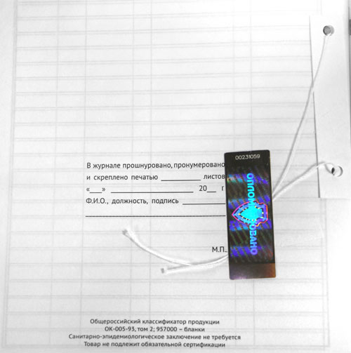
You receive printed products numbered, laced and prepared for sealing in accordance with the current regulatory documents:
The cost of lacing and fastening is 39 rubles.
?
Page numbering starts from the title page to the last page of the magazine. Page numbers are located in the lower corners of the magazine.
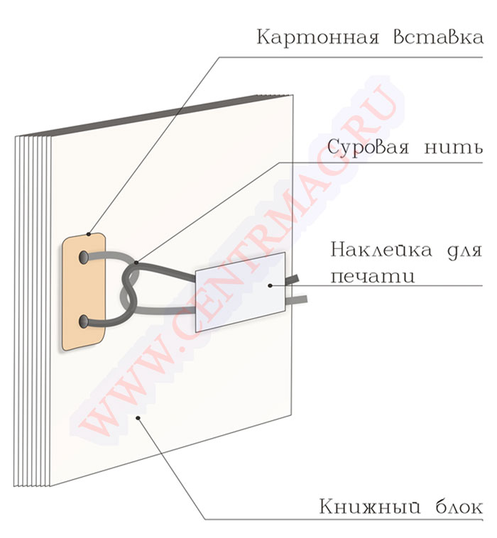
?The magazine block is punched through two holes with a diameter of 6 mm, which are located at a distance of 80 mm from each other, from the spine side in the middle of the magazine. 
?
The magazine is laced with a special lavsan thread threaded through the holes of the hole punch. Secure with a cardboard insert and a printable sticker. 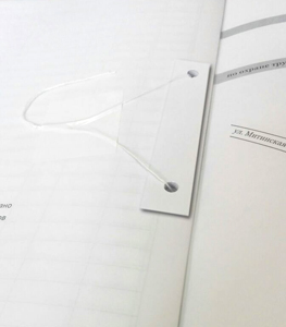
Number, lace, seal: ? According to the Decree of the Government of the Russian Federation of April 16, 2003 N 225 “On work books” Receipt and expense book for accounting of work book forms and inserts in it And book of movement of work books and inserts in them must be numbered, laced, certified by the signature of the head of the organization, and also sealed with a wax seal or sealed.
More about softcover Softcover- one of the most inexpensive and quickly produced bindings.
The binding cover is made of thick paper with a density of 160 g/m2; at your request, the cover can be laminated.
After the cover is ready and the block is printed, they are fastened with a paper clip, and if there are more than 60 pages in the block, then the bonding is carried out using a hot-melt adhesive machine.
Soft binding, due to its ease of execution and affordable price, is the most popular and one of the most affordable types of binding.