After completing all the necessary constructions, it is often necessary to print AutoCAD drawings. Printing output can be done in AutoCAD different ways: Either it will be a single print or a batch print. In the second case, printing AutoCAD drawings is done through “Publishing,” which allows you to simultaneously print multiple sheets from different files. In this article we will look at how to set up printing in AutoCAD
quickly and correctly!
AutoCAD - printing in accordance with GOST.
As you know, any drawing must be drawn up in accordance with GOST. One of the most pressing problems is to make strict indentations from the drawing frame to the edge of the sheet. After all, every printer has a small area that is not printed. It is needed so that the printer can capture the sheet. To achieve the desired result, printing settings in AutoCAD must be correctly configured. Let's look at this in more detail.
Print settings in AutoCAD. All necessary settings should be made in
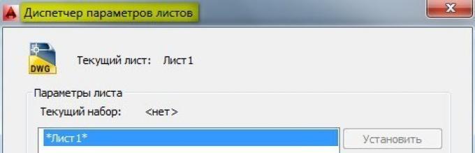
Sheet Settings Manager.
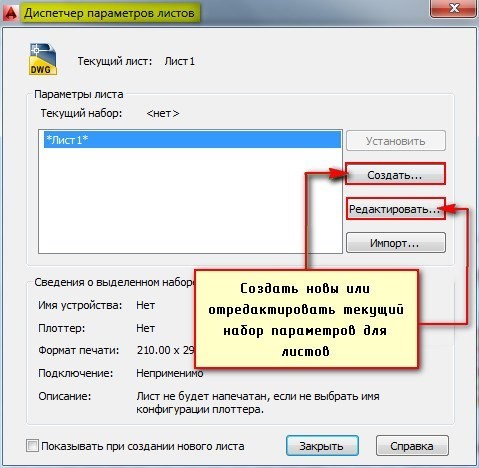
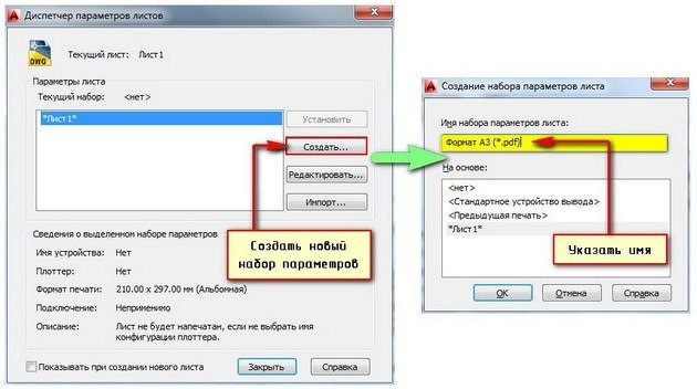
The Manager dialog box will open, in which you need to either create a new one or edit the current set of parameters. It is, of course, better to create a suitable set of all parameters for sheets once than to edit them every time. Select “Create”, then enter a name for the set and click “Ok”.
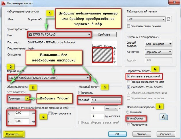
A window will open in which you need to make all the settings.
1) Select a printer. If no device is connected, you can select a driver that converts the drawing.
2) Specify the sheet format. You should select the appropriate one from the drop-down list. Moreover, international borderless ISO formats allow you to expand the boundaries of AutoCAD printing, as a result of which the location of the frame in the drawing will correspond to GOST.
3) The AutoCAD print area should be selected from the drop-down list. There are four options:
— Borders;
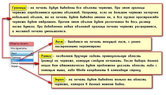
— Model;
You can click the “View…” button in the process of selecting a suitable option.
4) If necessary, indicate the offset of the drawing or center it.
5) Set the scale.
6) In the “Print Options” rollout, check the boxes next to the required actions. So, in order to display the actual line thickness when printing in AutoCAD, you should select “Take line weights into account.”
7) Select the drawing orientation (portrait or landscape).
I would like to note that the actual design of drawings should be done on customized sheets. Only in this case will it be possible to print them quickly and correctly.
Printing AutoCAD files
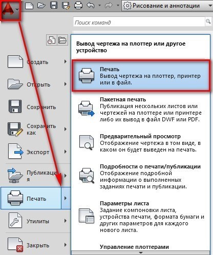
Let's look at an example of a single print. Let's switch to the sheet that needs to be printed, press the key combination Ctrl+P or Application Menu → Print...
The Print dialog box appears. Because We previously created a set of specific parameters and assigned it to sheets; we don’t need to configure anything else. Just click “Ok” and printing will start. If you selected the DWG To PDF driver, then your drawing will be converted to pdf format and you need to select a storage location for it on your computer.
As you can see, printing from AutoCAD is very easy! The main thing is to correctly configure the sheet parameters and you will not have any problems.
Printing sheets in AutoCAD (Publishing in AutoCAD)
If you are faced with the task of printing several drawings at the same time, then you should understand the concept batch printing in AutoCAD.
Publishing to AutoCAD. Setting up sheets.
If you want to perform a quick and correct printing several sheets in AutoCAD, then you first need to set up the Sheet space, which is intended directly for designing drawings and printing them. By default, any drawing contains two A4 sheets named “Sheet1” and “Sheet2”.
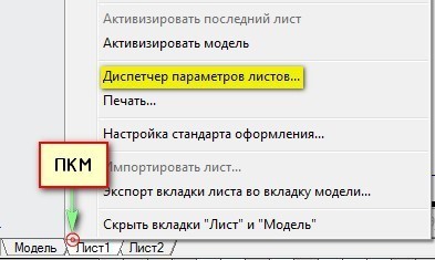
Right-click on the Sheet tab and select “Sheet Parameters Manager...”
RMB on the Sheet tab and select "Sheet Settings Manager..." in AutoCAD
In the Manager dialog box, you need to create a new set of parameters. This will allow you to optimize your work with sheets, because... The set provides the ability to configure the necessary parameters once, and then assign them to newly created sheets.
Click “Create”, then enter a name for the set and click “Ok”.
Click New and provide a name for the new sheet preset in AutoCAD
The Sheet Options window opens. First of all, in the “Printer/Plotter” tab, in the “Name” field, select the connected device. If no printer is connected, then select the DWG To PDF driver. In this case, the drawing will be saved in the universal *.pdf format. The second important step is to select the appropriate format.
Printing in AutoCAD It has a large number of various settings. It is not possible to cover everything in one lesson. Therefore, in this article we will look at one of the possible options for organizing specification printing. We discussed creating specification tables in AutoCAD and Excel, and establishing connections between them in the previous lesson:.
You can download the linked Excel and AutoCAD specification files for free.
To print a specification in AutoCAD, you first need to create Sheets in which the parameters for their printing will be specified. So in this tutorial we will look at:
Creating the first specification sheet.
Let's prepare several specification sheets for printing, according to GOST. Open the "Spec.dwg" file. Go to the "Sheet1" tab. To rename a tab, double-click on it. Once the tab name is highlighted, enter a new name. See Fig. 1.
Rice. 1. Renaming the Sheet.
I renamed "Sheet1" to "Sp1".
Let's set the printing parameters for this sheet.
Place the cursor on the "Sp1" tab and click the right mouse button. From the context menu, select " Sheet Settings Manager..." See Fig. 2.
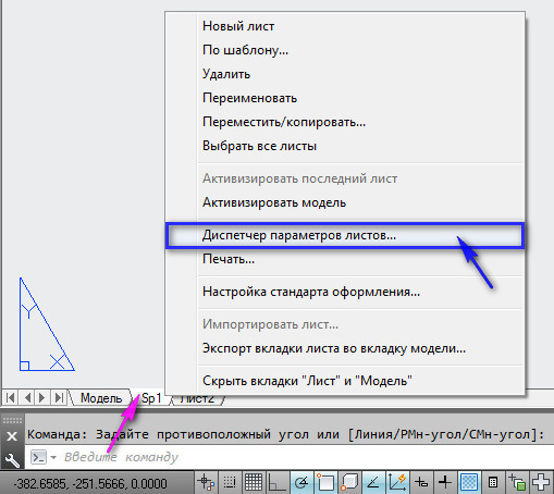
Rice. 2. Context menu.
The Sheet Settings Manager opens. Here we can create a named set of print parameters and subsequently pass these parameters to the necessary sheets. Click on the “Create” button.
In the “Create a set of sheet parameters” window, enter a new “Name of the set ...” (“Spec”) and click OK. See Fig. 3.
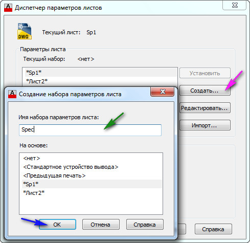
Rice. 3. Create a set of sheet parameters.
The “Sheet Options – Sp1” window will open. Select plotter(printer) on which the sheet will be printed. Set the sheet size (A3) And orientation (Landscape). Select print style (acad.ctb). After all the sheet parameters are set, click OK. See Fig. 4.
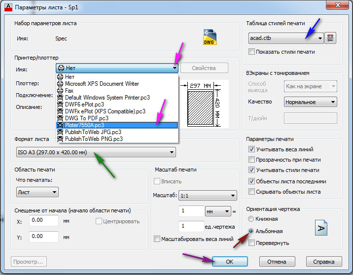
Rice. 4. Sheet parameters.
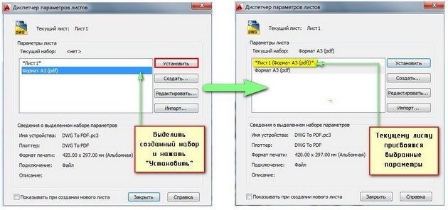
In order to transfer the printing parameters “Spec” to the sheet “Sp1”. In the Sheet Options Manager, select the sheet options “Spec” and click the “Set” button. The "Spec" parameters will be passed to the current sheet "Sp1". Click the "Close" button. See Fig. 5.
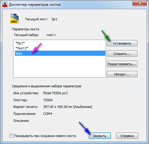
Rice. 5. Transferring parameters to the current sheet.
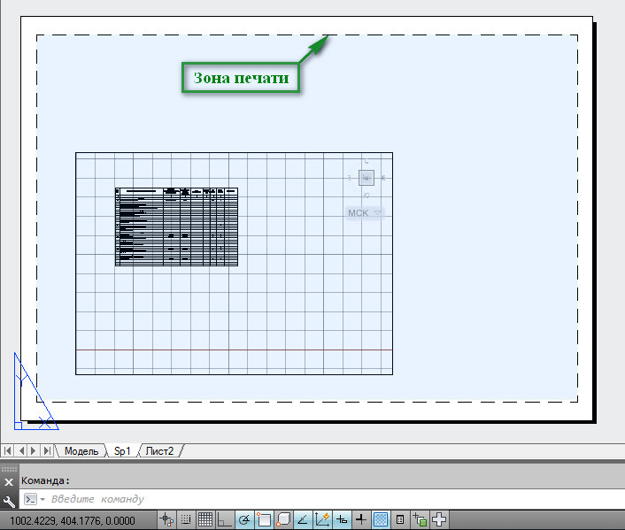
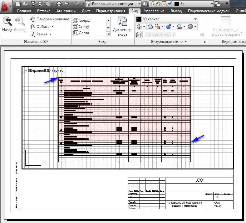
Rice. 6. Printing area.
We draw a standard frame with a stamp in accordance with GOST.
Highlight " Viewport area" by clicking on its border. Then highlight top right handle And move it to the top right corner of the inner frame See Fig. 7.
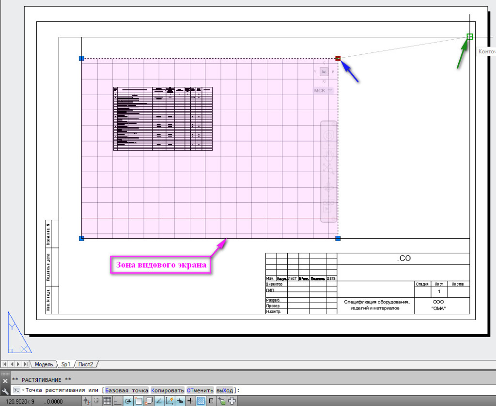
Rice. 7. Changing the size of the Viewport area.
Using the left, upper corner of the viewport area, stretch it to the left, upper corner of the inner frame. Then double click inside the Viewport. It will be highlighted with a bold line. Next on the ribbon, go to the “View” tab, click on the arrow that reveals navigation modes and select the “Frame” line. See Fig. 8.
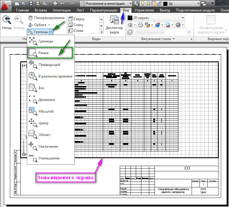
Rice. 8. Working inside the Viewport.
Then indicate with a frame that part of the table, which you want to stretch across the entire Viewport Area. See Fig. 9
Rice. 9. Working inside the Viewport.
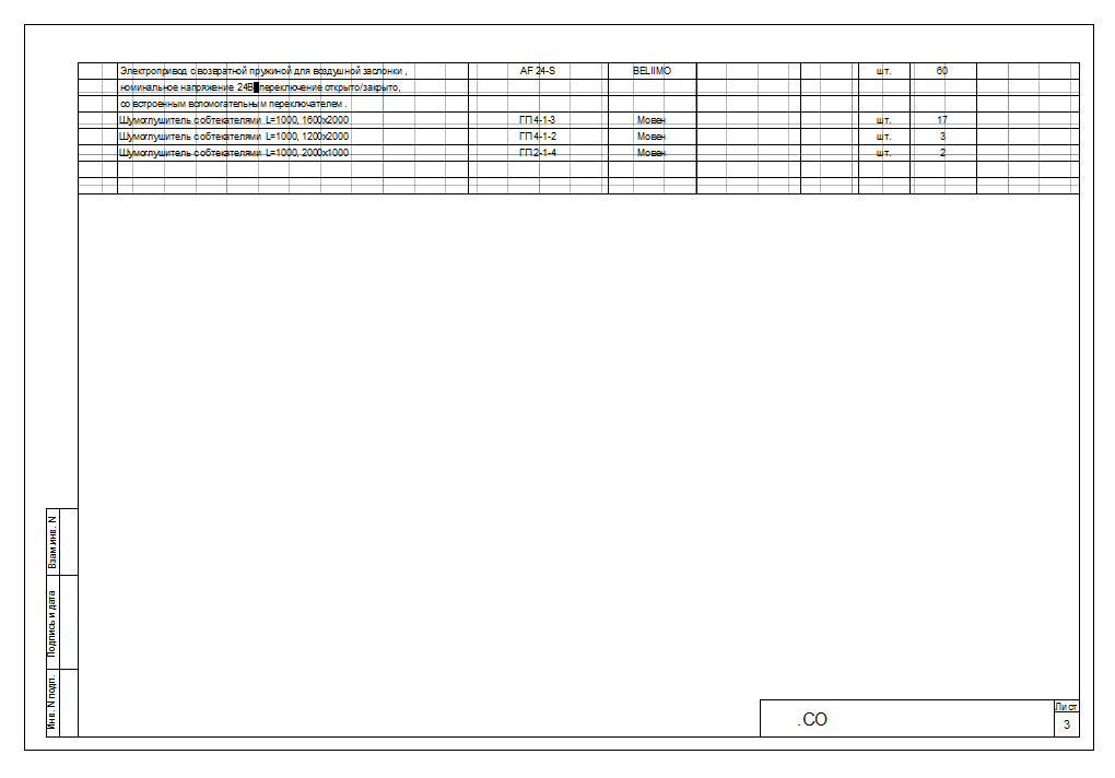
As a result, we get approximately the following. See Fig. 10.
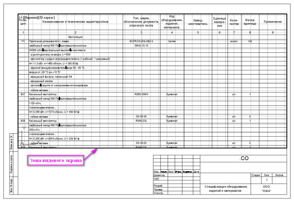
Rice. 10. Part of the table occupies the entire Viewport area.
All we have to do is raise (or lower) the bottom line of the Viewport a little. To do this, double-click outside the Viewport Zone to exit it. Next, click on the Viewport border to make the handles appear. Highlight the bottom handle(click on the handle so it turns red), lift it up a little and click in a new location. See Fig. eleven.
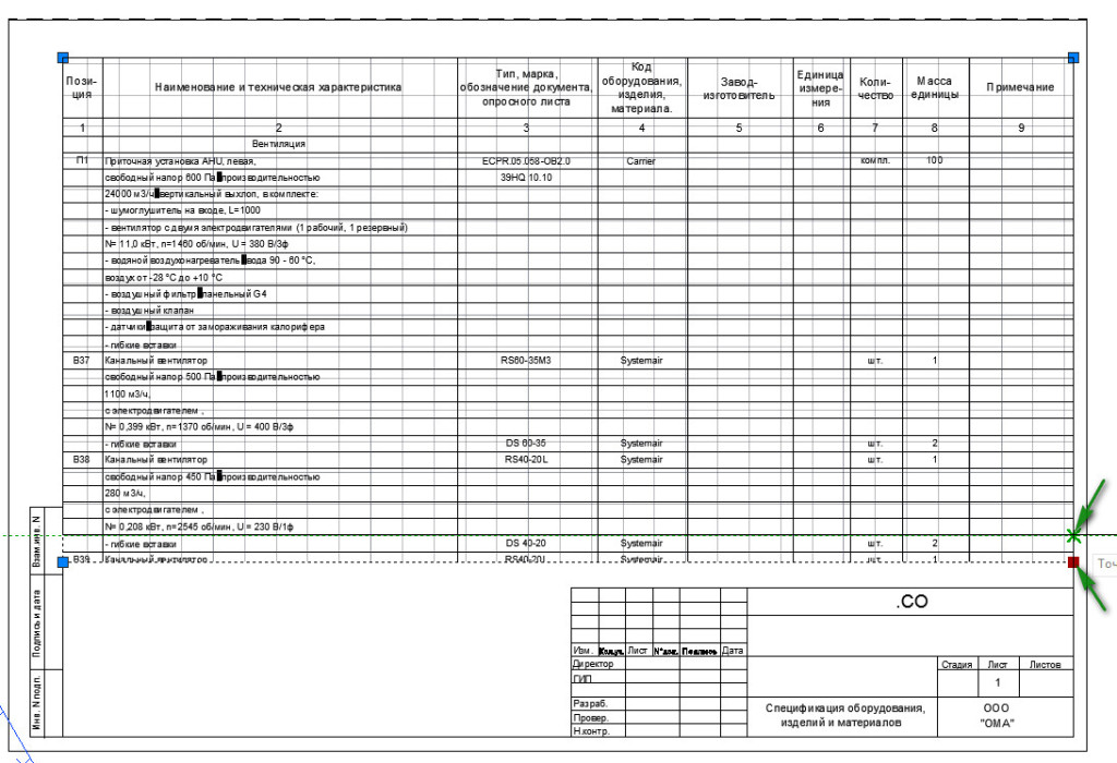
Rice. 11. Changing the Viewport Zone.
To deselect the Viewport, press on your keyboard
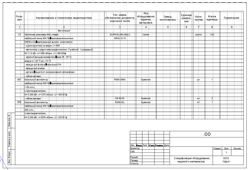
Rice. 12. First specification sheet.
Creating a second specification sheet.
Let's start creating the second sheet. The easiest way is to make the second sheet based on the first. So first, let's make a copy of the "Sp1" sheet. To do this, place the mouse cursor on the “Sp1” tab, click left mouse button and a key
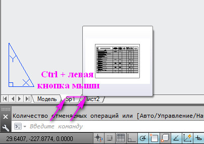
Rice. 13. Make a copy of the Sheet.
As a result, we will get a copy of the sheet “Sp1” (“Sp1(2)”). Let's rename it "Sp2". Double-click the sheet name ( "Sp1(2)" stand out) and enter a new name.
Then select the stamp and press the key (Delete). See Fig. 14.
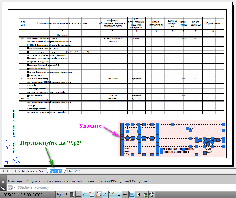
Rice. 14. Remove the stamp.
The stamp will disappear, and in its place draw a stamp for the second sheet specifications. Then double click inside the Viewport Zone. Click middle mouse button(the “Panning” function will turn on), and without releasing it, lift the rest of the table up. (If you don’t have a middle button on your mouse, go to the “View” tab on the ribbon and click on the “Pan” button) See Fig. 15.
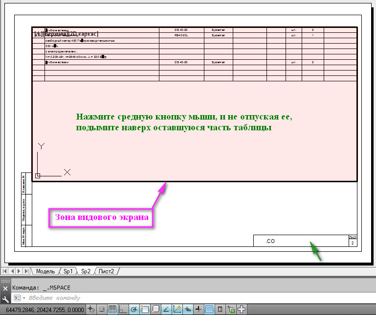
Rice. 15. Move the table inside the Viewport.
Highlight the bottom handle(click on the handle so it turns red), move it up to where the table ends and click in the new location. See Fig. 16.
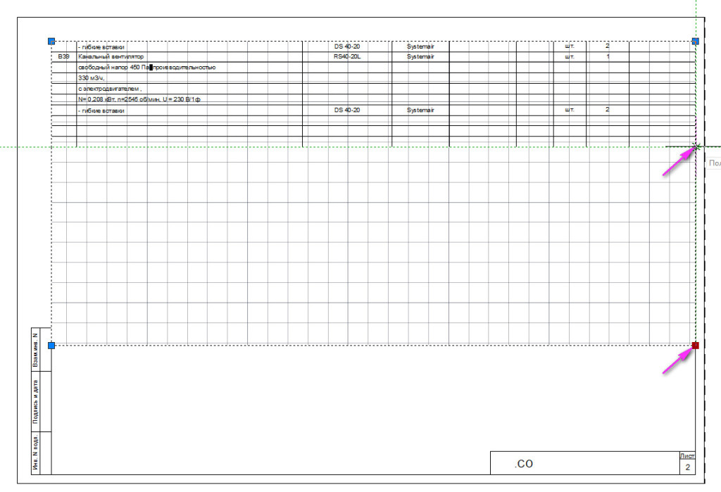
Rice. 16. Changing the Viewport Zone.
Rice. 17. Second specification sheet.
Adding and changing data to specifications.
If you need to add or change data in the specification, open the Excel file “Spec.xls”, make the necessary changes, and save it (I added the data to the specification).
Let's return to AutoCAD.
Go to Model space.
Select the table, go to the “Annotations” tab and click on the “ Download from source" See Fig. 18.
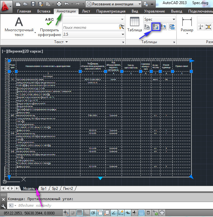
The data from Excel will be loaded into the AutoCAD table.
To move text to the left in the second column, select the required cells, the Table Cell tab appears. Click on the button text placement controls and in the list that appears, select “Middle Left". See Fig. 19.
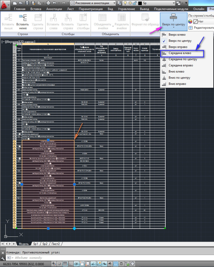
Rice. 19. Table formatting.
The text in the selected cells will move to the left. Then go to the "Sp2" sheet, click on the Viewport border so that the handles appear. Highlight the bottom handle(click on the handle so it turns red), lower it down to the stamp and click in the new location. See Fig. 20.
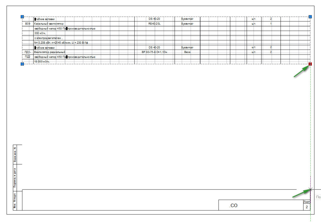
Rice. 20. Changing the Viewport Zone.
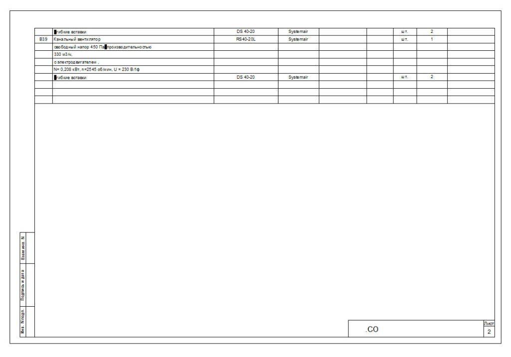
The second specification sheet will look something like Fig. 21
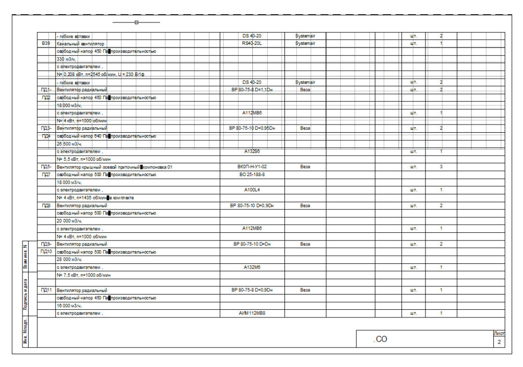
Rice. 21. Second specification sheet.
But we see that the specification table did not fit on two sheets. Therefore, we create the third based on the second.
Creation of the third specification sheet.
Make a copy of the second sheet. To do this, place the mouse cursor on the “Sp2” sheet tab, click left mouse button and a key
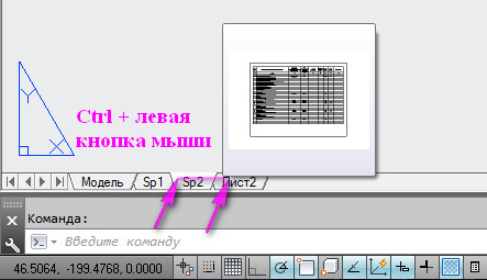
Rice. 22. Make a copy of the Sheet.
As a result, we will get a copy of the sheet “Sp2” (“Sp2(2)”). Let's rename it "Sp3". In the stamp “2” correct it to “3”. Double-click inside the Viewport Zone. Click middle mouse button, and without letting her go, move up the rest of the table. (If you don’t have a middle button on your mouse, go to the “View” tab on the ribbon and click on the “Pan” button) See Fig. 23.
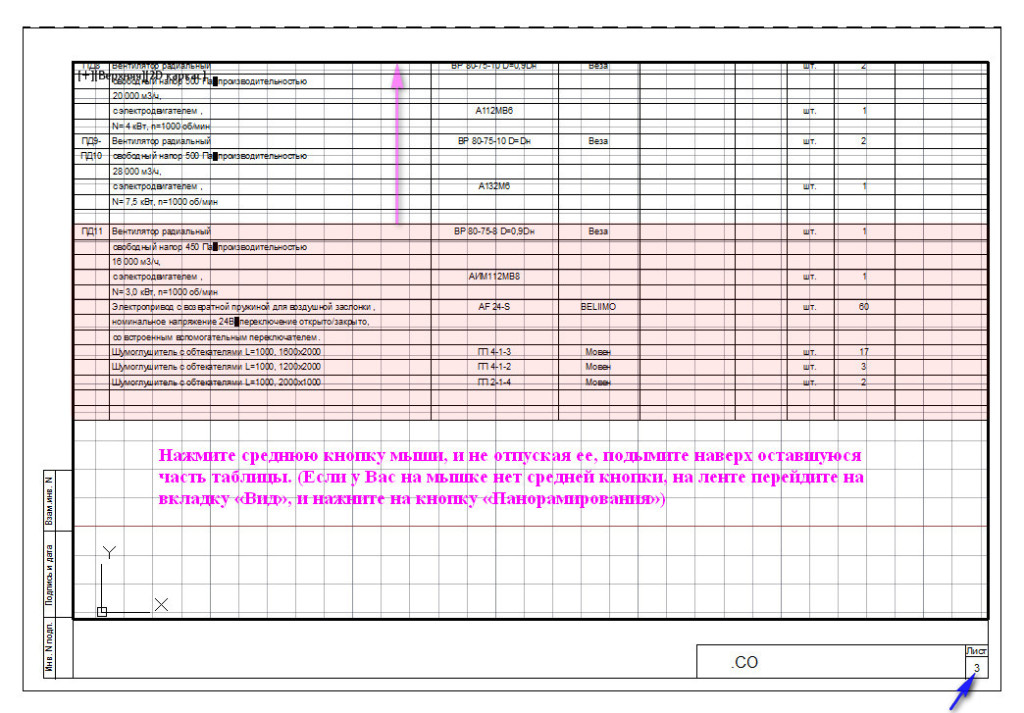
Rice. 23. Move the table inside the Viewport.
Once you have positioned the table correctly, double-click outside the Viewport Zone to exit it. Next, click on the Viewport border to make the handles appear. Highlight the bottom handle(click on the handle so it turns red), lift it up, to the place where the table ends and click in new location. See Fig. 24.
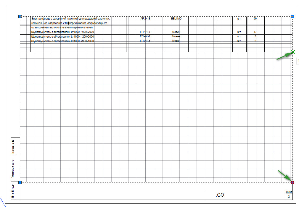
Rice. 24. Changing the Viewport Zone.
To remove selections from the Viewport, press on your keyboard
Rice. 25. Third sheet of specification.
If the specification does not fit on three sheets, then we create as many sheets as necessary.
Print one sheet.
Go to the sheet tab that you want to print (For example, “Sp2”) and press Ctrl+P on your keyboard (press the Ctrl key and hold it down while pressing P). The “Print – Sp2” window will open. All parameters have already been set and to print the sheet, just click on the OK button. You can preview how the printed sheet will look by clicking on the “Preview...” button. See Fig. 26.
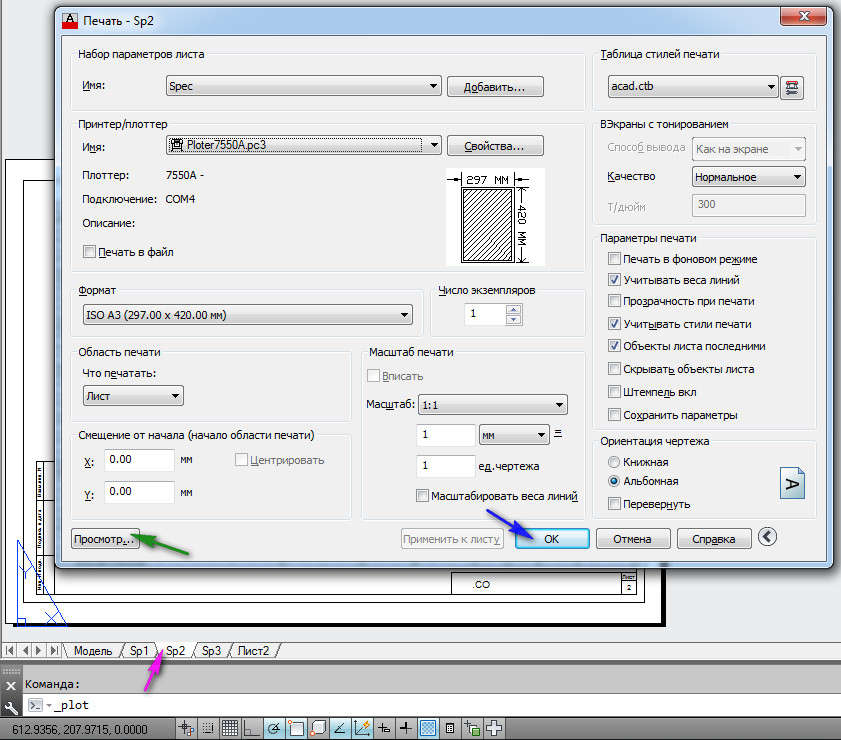
Rice. 26. Print Leaf.
Click OK and the “Sp2” sheet will print.
In today's lesson we'll talk about the Sheet space in AutoCAD, creating new sheets and working with them.
AutoCAD provides two workspaces for working with drawings. This Model and Sheet space. All constructions are made in the model. And paper space in AutoCAD is used to layout the drawing before printing.
At the same time, it is convenient to draw all objects in model space with a scale of 1:1, and then scale and design the drawing on sheets. There are, of course, some peculiarities here. But we will look at them in another lesson.
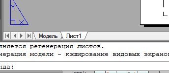
The transition to the sheet is carried out using bookmarks under the graphic area of the drawing. You can create multiple sheets with different layouts. But by default, there are always two of them created - Sheet 1 and Sheet 2.
When you go to one of the sheet tabs, a dialog box usually appears Sheet Preset Manager. Serves just for setting up sheets before printing.
Close it for now, we'll look at it in the next lesson.
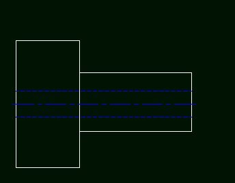
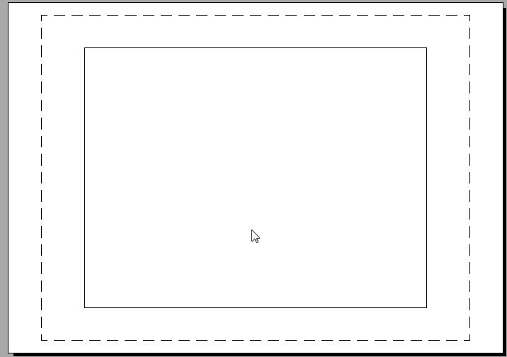
Now we have in front of us a white sheet with a dotted frame and a rectangle containing our drawing.
So... The white sheet is our sheet of paper on which everything will be printed. The dotted frame defines the visible print area. A rectangle with a drawing inside is viewport.
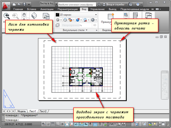
Viewport- this is a kind of fixed view of the drawing or part of it from the model space. Moreover, it is possible to fix different types of the same objects, for example, a floor plan with load-bearing walls and partitions or a floor plan with only load-bearing walls. These types can be placed on one sheet or on different ones. This is a very big plus in using sheets in AutoCAD.
By default, one viewport is already created on the sheet. And the drawing from the model space is presented in it at an arbitrary scale.
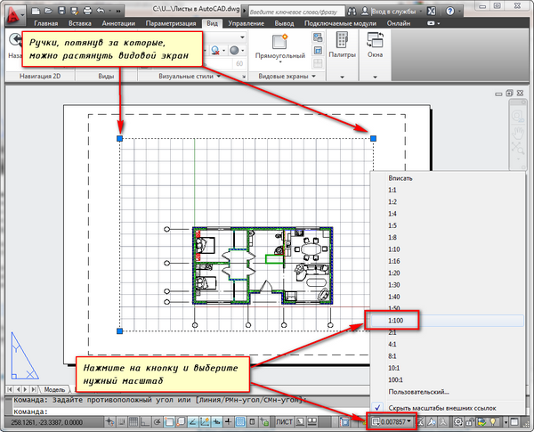
The viewport rectangle itself can be enlarged or stretched using handles. And then choose the scale with which the drawing should be presented on the sheet. To do this, select the viewport and set the desired scale. For my example I will take 1:100.
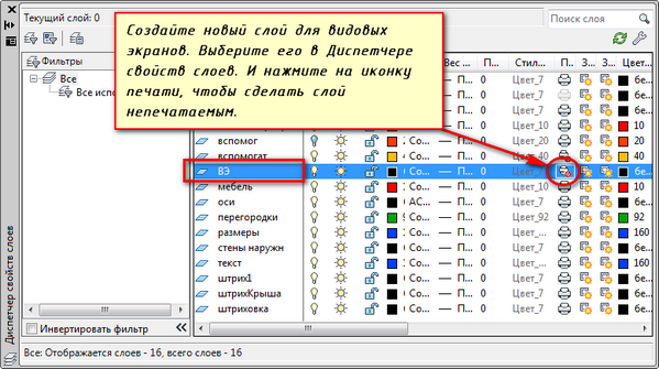
The layer containing the viewport rectangle can be made non-printing. In this case, the frame itself will remain visible on the sheet, but when printed on paper it will not be visible. To do this, create a new layer with a name, for example, VE. And click on the print icon in Layer Properties Manager.
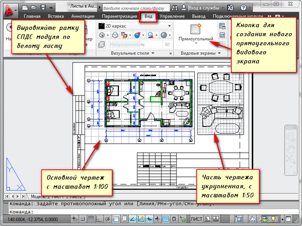
It is convenient to first place a frame with a stamp on the sheet, fill out the stamp, and make some inscriptions. Then enter the drawing with the desired scale using viewports.
If you need to show some node of an object on the same sheet, then there is no point in drawing it in the model again with an enlarged scale. It is enough to simply create another viewport and display this node on it with a different scale.
True, there will be some difficulties with the so-called out-of-scale elements. This is text, line types, shading, dimensions, etc. But more on this in the next part of the article about working with sheets in AutoCAD.
Here is my example with a drawing on a sheet. I took the frame from the SPDS module, which can be downloaded and installed from the Autodesk website.
Another handy use of sheet viewports is the ability to freeze individual layers.
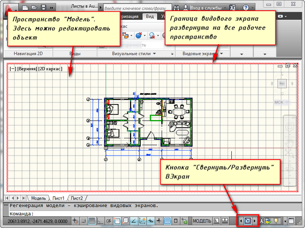
Let's go to the viewport. To do this, double-click the left mouse button inside the viewport frame. It is highlighted with a bold line.
And now you can edit the object here.
Those. You are currently in model space. For convenience, you can expand the viewport border to cover the entire workspace. To do this, click on the “Expand VScreen” button on the status bar. To return to the sheet, click the "Collapse VScreen" button.
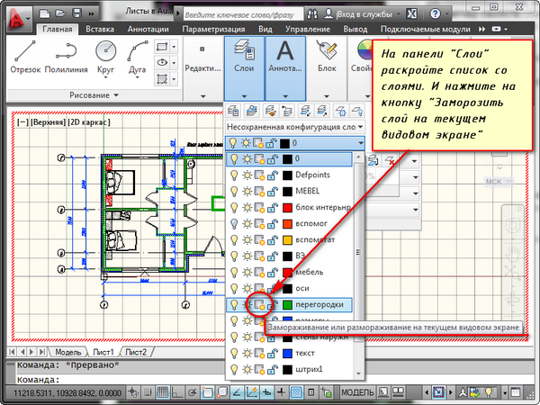
We need to freeze some of the layers. For example, internal partitions. Click on the layer freeze icon. And the layer seems to disappear. But it only disappears in the active viewport. In the new screen it will already be visible.
HOW TO CREATE A NEW SHEET IN AUTOCAD?
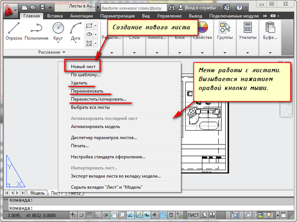
Hover your mouse over a tab, for example, sheet 1. And right-click. The menu for working with sheets will open. Here, select New Sheet. Provide a name for the Sheet and press "Enter".
You can also create a new sheet in AutoCAD by entering the RLIST command.
You will be prompted on the command line: "Enter the parameter for the sheet [Copy/Delete/New/Template/Rename/Save/Set/?]<установить>".
In response to it, indicate the key letter for calling the desired option of the RLIST command.
Thus, you can copy, delete, rename sheets.
Now you know how to create a new sheet in AutoCAD. You can also save the sheet with the configured parameters as a template, and then use it in further work.
After you have drawn all the views, sections and plans of the object, the question of drawing up the drawings arises. About how this is done, what formats autocad sheets in this case, they are used and how to rearrange the drawing onto a sheet of a smaller format while maintaining the scale of the drawing will be discussed in this article. If you want to know more about the format autocad files, how else can you open and edit them, we recommend that you familiarize yourself with this material.
It is best to arrange autocad drawing on the Layout tab using viewports. This is done as follows:
Right-click on the sheet tab and select the By template menu item.
We will use a ready-made Autocad sheet format file, which we can quickly download from here. We save it on the computer, copy it to the clipboard by pressing Ctrl+C and paste it into the Template folder, which will open after selecting By Template. You can paste directly in this window by pressing Ctrl+V. Select the copied template, click open and then in the window that appears, click on the sheet of the desired format and orientation. 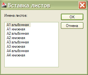
After these steps, we create a viewport using: Ribbon - View - Viewports - Create or the Viewports toolbar, read how to display it. Next, we define a rectangular viewport area for each of the views drawn on the Model tab. It is better to create this area in the Defpoints layer so that the viewport boundaries are not printed when output to the printer. Then we double-click inside the viewport and place the required drawing view in it. We set the view scale as shown in this figure: 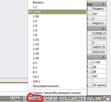
Thus, we place all views in viewports, giving them the required scale. At the same time, it is easy to select the autocad sheet format.
However, there are many users who do not use the generation of AutoCAD drawings on sheets in their work. They either find it inconvenient or don't want to figure out how to arrange drawing views on the Sheet tab. They arrange the drawings directly on the Model tab, while in Autocad they increase the format of the drawing frame by the required number of times, 100, 50, 25, 10, in order to place the drawing views drawn on a scale of 1:1. At the same time, they create autocad text and dimension styles, enlarged by the same number of times as the drawing frame. Since this approach is convenient for someone, it probably has a right to exist. These autocad sheet formats can be downloaded from the link. The file contains frame formats A1, A2, A3, A4 in landscape and portrait orientation.
It is also worth saying that sometimes the task arises of rearranging drawings made on large Autocad A1 or A2 formats to A3 due to the basic lack of equipment for printing large drawings. If you simply write a drawing onto an A3 sheet when printing, then, firstly, the scale of the drawing will not be maintained, and secondly, the views will turn out small, difficult or completely unreadable. Therefore, the drawing must be rearranged into several A3 formats while maintaining the scale. Therefore, the question arises: How to turn an A1 format frame into A3. There is a simple relationship - the area of each subsequent sheet format increases by √2=1.414 times. Those. to turn the A1 format into A3, you need to successively reduce it by 1.414 times, using the Scale tool, scale it twice with a factor of 0.707 = 1/1.414. When scaling, do not select the drawing stamp to maintain its original scale.
Now we have everything we need autocad formats to generate drawings in accordance with GOST and putting together any drawing will not be a problem. You will also be able to quickly rearrange any drawing onto A3 format while maintaining the scale of the views.
Find out also in this section:
This lesson is dedicated to working in AutoCAD with paper space.
To begin with, what is the advantage of working with sheets in Autocad:
- Working with sheet space makes it easier to print, that is, output the drawing to a printer or plotter. Since in this case the entire sheet is printed. On a sheet, we arrange as many drawings as we need to display at a time, while it remains possible to print one drawing, as in model space using a window frame.
- Is it convenient that we draw the part on a scale of 1:1? and then insert the required view of the drawing at the scale we need using the “viewport”.
One of the disadvantages for myself is that it is better not to delete anything from the model space if you don’t know, as this may affect some drawing. Also, sometimes the scale or dimensions with icons drawn on the sheet and not in the model disappear, if the viewport is not fixed.
How to work with paper space in autocad.
To switch to paper space click the sheet1 tab
So let's go to paper space.
We see in front of us a white sheet and two rectangles: dotted and regular.
If something was drawn in the model space, then it should also automatically fall into the visibility area viewport, that is, it will appear on the sheet.
Now let me explain. A white sheet is a sheet whose dimensions can be set to any size based on the paper size on your printer.
The dotted rectangle is print visibility area, and a regular rectangle is viewport.
Viewport like a “window into the model area”. By double-clicking on it, we configure the view we need at the required scale. We select an arbitrary scale with the mouse wheel or set the required one with a number.
You can create as many viewports as you like, if let’s say we need to show several views at different scales.
To create a viewport, we need to add the Autocad "Viewports" panel
This panel also has functions for trimming the viewport to give it the desired shape. The required scale is also driven in here.
After working with paper space, I set myself the following order of work:.