Gravity and weight
According to the law of universal gravitation, all bodies on Earth experience the force of its attraction.
The force of gravity of a body is a measure of its attraction to the Earth (taking into account the influence of the Earth's rotation):
G = tg;[ G] = ML T-2.
Sipa gravity depends on the masses of the Earth and the body attracted by it, as well as on the distance between them. The distance from the center of the Earth to its surface is less at the pole (6357 km), and more at the equator (6378 km), so the gravitational force at the equator is 0.2% less than at the poles.
Since the Earth rotates around its axis, the bodies on its surface experience the centrifugal force of inertia (fictitious) in a non-inertial (rotating) frame of reference. It is greatest at the equator and reduces the force of gravity there by another 0.3% (compared to the position at the poles). Therefore, the force of gravity is equal to the geometric sum of the forces of gravity (gravitational) and centrifugal (inertial).
Gravity forces act on each link and on the entire human body as external forces caused by the attraction and rotation of the Earth. Equally acting parallel forces of gravity of a body are applied to its center of gravity.
When a body rests on a support (or is suspended), the force of gravity applied to the body presses it against the support (or lifts it off the suspension). This action of the body on the support (lower or upper) is measured by the weight of the body . Body weight (static) is a measure of the impact of a body at rest on a resting support (or suspension), which prevents it from falling. This means that the force of gravity and the weight of a body are not the same force. The weight of the whole body of a person is applied not to himself, but to his support (gravity is a distant force, weight is a contact force). There is no weight in the flight phase in running, this is a case of weightlessness.
When the head acts on the cervical vertebrae, the head and spinal column interact. Thus, the weight of the head relative to the entire body of a person is an internal force, while relative to the spinal column it is external. The weight, for example, of a barbell held by a person, for him, of course, is an external force.
When a body moves with an acceleration directed along the vertical, a vertical force of inertia arises. It is directed in the direction opposite to the acceleration. If the force of inertia is directed downward, then it is added to the static weight; the pressure force on the support increases. If the force of inertia is directed upwards, then it is subtracted from the static weight; the pressure force on the support decreases. In both cases, the changed weight is called dynamic, it is greater or less than static. The dynamic weight of the bar in the hands of the athlete acts on him from the outside (external force). The dynamic weight of the torso when jumping up acts on the legs inside the body ( inner strength relative to the whole body and external - relative to the legs).
Support reaction forces
The action of the body weight on the support meets a counteraction, which is called the support reaction (or support reaction).
Support reaction- it is a measure of counteraction of a support to the action of a body that is in contact with it (at rest or in motion). It is equal to the force of the body acting on the support, directed in opposite side and attached to this body.
Usually a person, being on a horizontal support, experiences resistance to his weight. In this case, the support reaction, like the weight of the body, is directed perpendicular to the support. This is the normal (or ideal) support reaction. If the surface is not flat, then the support reaction is perpendicular to the plane tangent to the fulcrum.
When the weight is static, the support reaction is static; it is equal in magnitude to the static weight. If a person on a support moves with an upward acceleration, then the inertial force is added to the static weight and a dynamic reaction of the support occurs. The support reaction is a passive (reactive) force. It cannot in itself cause positive accelerations. But without it - if there is no support, if there is nothing to push off from (or nothing to be attracted to) - a person cannot actively move.
If you do not push straight up from the horizontal support, then the pressure force on the support will not be applied at a right angle.
to its surface. Then the reaction of the support will also not be perpendicular to the surface, it can be decomposed into nanonormal and tangential components. When the contacting surfaces are even, without protrusions, spikes, etc. (asphalt, shoe sole), then the tangential component of the support reaction is the friction force.
The tangential reaction can be caused not only by friction (as, for example, between a ski and snow), but also by other interactions (for example, the spikes of running shoes stuck into the track).
The resultant of the normal and tangential components is called the general reaction of the support. It only passes through the human CM only when it is in a free stationary position above the support (or under the support). During movements, repulsion or depreciation, it usually does not pass through the CM, forming a moment relative to it.
Let's get acquainted with the law that allows you to calculate the force of friction. It was discovered by the Frenchman G. Amonton and tested by his compatriot C. Coulomb, therefore it is called the Amonton-Coulomb law.
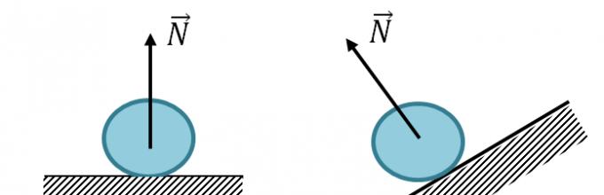
Consider a body lying on a support (see the left side of the drawing). The body acts on the support with its weight W, which is directed downwards. According to Newton's third law, the support reacts force on the body R, equal in modulus to the weight of the body and oppositely directed. According to the parallelogram rule, the reaction force R can be represented as the sum of the normal reaction force N perpendicular to the surface and tangential reaction forces T along the surface. This part of the reaction is static friction force.
If we place the support horizontally, then it will also react to the body according to Newton's third law (see the middle part of the drawing). In this case, as before, the support reaction force R will be equal in absolute value to the weight of the body W and oppositely directed. Along with this, the reaction force will simultaneously be the normal reaction force, and the tangential reaction force, the friction force, will be absent. If now an external force F directed along the surface is applied to the body, then we will again cause the appearance of a tangential reaction force. In this case, she will sliding friction force(see the right side of the drawing).
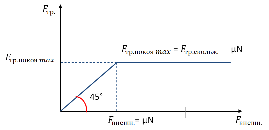
Experiments show that when one body moves on the surface of another the modulus of the sliding friction force is proportional to the modulus of the normal reaction force of the support, expressed as Amonton-Coulomb law:
In other words, the Amonton-Coulomb law indicates the proportionality of two forces: the tangential support reaction (sliding friction force) and the normal support reaction (pressure force).
- Previously, we could only measure the force of friction, now ...
- The Amonton-Coulomb law is called double because...
- To clarify the new designation in the formula of the law, ...
- If the body is at rest, it acts on the support with only one force - ...
- Since not only the body acts on the support, that is, there is an interaction, then ...
- Using the definition of the resultant for two forces "in reverse", ...
- The tangential component of the support reaction force is...
- With a horizontal position of the support, its reaction force, as in the first case, ...
- In the second case, according to the rule for finding the resultant, ...
- The drawing on the right shows...
- The tangential component of the support reaction in the right drawing is...
- Formulate the Amonton-Coulomb law.
- The formula of the Amonton-Coulomb law is scalar, since it includes ...
- The formula of the Amonton-Coulomb law from the point of view of mathematics ...
Forces in mechanics
Any body located near the surface of the earth or lying on the ground is affected by a force equal to the product of the mass of the body and the acceleration of free fall:.
\vec(F)_(T)=m\vec(g)
2. Support reaction force (normal reaction, support elasticity)
The force acting on the side of the support on the body lying on it. Always directed perpendicular to the contact surface of the body and support.
\vec(N) - support reaction force.

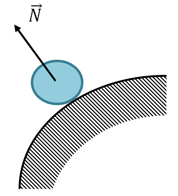
If the body lies on the inner surface of the sphere, the force \vec(N) is directed towards the center of the sphere.

If the body lies on the outer surface of the sphere, the force \vec(N) is directed from the center of the sphere.
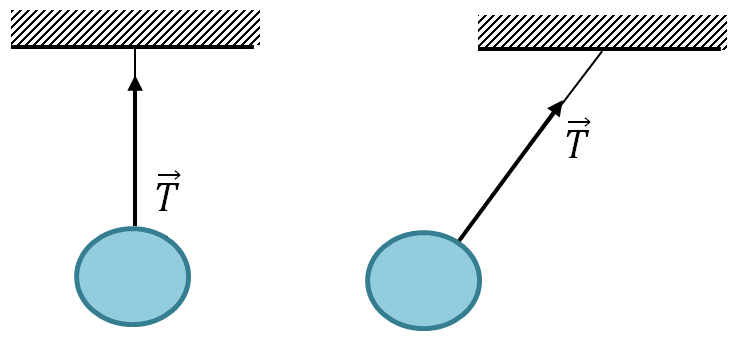
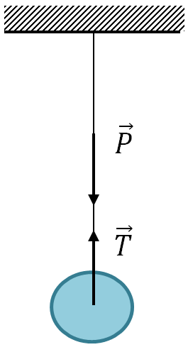
The force acting from the side of the thread (rope, rope, cable, rod, etc.) on the body that hangs on the thread (rope, etc.). Directed along the thread (etc.).
\vec(T)
4. Body weight
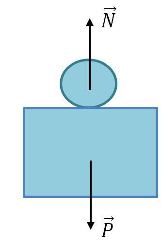
Definition: is the force with which the body presses on the support or stretches the suspension.
The weight of the body is equal in absolute value to the support reaction force or the thread tension force, is directed in the opposite direction and is applied to another body: either the support or the thread.
\vec(N) - support reaction force;
\vec(P) - body weight.
\matrix(\vec(P)=-\vec(N)\\\mid\vec(P)\mid=\mid\vec(N)\mid)
\matrix(\vec(P)=-\vec(T)\\\mid\vec(P)\mid=\mid\vec(T)\mid)
5. Force of friction
a) Sliding friction force
The force of sliding friction is directed opposite to the relative speed of the bodies and does not depend on the area of contact between the surfaces.
\vec(F)_(tr)
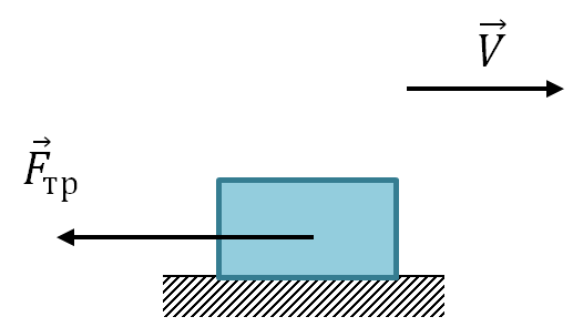
The modulus of the friction force is equal to the product of the coefficient of sliding friction and the modulus of the reaction force of the support:
\vec(F)_(tr)=\mu N
\mu - coefficient of sliding friction.
b) Rolling friction force
It acts on a body that does not slide, but rolls on a certain surface.
\vec(F)_(tr)
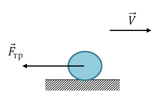
\vec(F)_(tr)=\mu _(1)N
\mu _(1) - coefficient of rolling friction.
The coefficient of rolling friction is much less than the coefficient of sliding friction
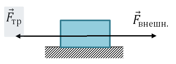
c) The force of static friction
It acts on a body lying motionless on some surface, which we are trying to move. It is opposite to the external force and is equal to it in absolute value.
\vec(F)_(tr.p.)
\vec(F)_(external) - external force.
6. Scheme for solving problems
a) Draw all the forces applied to all the bodies of the system;
b) Choose reference systems (you can have your own for each body);
c) Project the forces on the axis;
d) Write equations for Newton's second law in projections for all bodies of the system;
e) Write down the kinematic relationships, that is, the relationships between the velocities and accelerations of various bodies in the system;
f) Solve the resulting system of equations.
Reviews
|
Alexandra |
|
Natalya Lvovna is a wonderful teacher who will perfectly prepare you for the exam. I came to her not with zero knowledge, but they cannot be called good. Although I started studying in January, we managed to go through all the topics in additional classes. Each topic was analyzed and all types of problems that could be encountered on the exam were solved. And indeed, at the Unified State Examination, I did not encounter difficulties in solving problems and wrote an exam for 94 points. I highly recommend this teacher! |
|
Ilya |
|
I started studying with Natalya Lvovna in mid-January, right after the New Year holidays. Before the start of classes, there were trial exams in physics, as well as preparation for the exam at school, but the result was 60-70 points, while I received excellent marks in the subject. Classes with Natalia Lvovna were fruitful and interesting, with this tutor I was able to expand my knowledge of physics, as well as consolidate the school curriculum. Having passed the spring intensives, I went to the exam confident in my result. Having received 85 points, I was able to enter the desired university with 1 wave. I want to once again thank the tutor who helped me get closer to my goals, pass the single State exam on the necessary points, enter a university and start training for a future profession. |
|
Tatyana |
|
My daughter Polina studied at a school with a "humanitarian bias". The main subjects from the first grade for her were foreign languages. But, when the question arose of choosing a profession, the daughter wanted to enter a technical university. It's obvious that school program- not rubber, and it is not surprising that with 8 training hours foreign languages she only had one physics lesson a week. I had to urgently look for a solution. We were lucky - we found a wonderful tutor. |
Support reactions.
We found out, however, it was known even without us that everything has a limit. Beyond the limit, a person has death, a building structure has destruction, but everyone is fighting for life. When we pressed the ruler with our finger in one of the places where the ruler rested on the books, we failed to defeat the ruler and with our finger we felt how the ruler rested, but did not bend a millimeter. Moreover, the more we pressed on the ruler, the stronger it rested, while the force with which we pressed on the ruler was comparable to the rebuff force.
In the real world, everything is very complicated - any substance, even a very simple one, has a very incomprehensible structure. Some substances consist of atoms connected in a crystal lattice, while the material can be single-crystal or polycrystalline. In other substances, atoms are part of molecules, which can be both simple and very complex. But between all these atoms or molecules there is a strict connection. All these atoms and molecules keep at a distance determined by nature, and when we put our finger on the ruler, we try to reduce the distance between atoms or molecules, but the molecules and atoms do not want this and resist, saying scientific language tension arises, i.e. the distance between atoms or molecules decreases, but if the finger is removed, then the atoms and molecules will return to their places.
Moreover, when we put pressure on the ruler, deformations occur not only in the substance of the ruler, but also in the book, in the place where the ruler rests on the book, in the substance of the table on which the books lie, and so on, up to the very core of the earth. By the way, for some substances, the term voltage can be taken literally - this effect is the basis for the operation of piezoelectric elements, but we will not be distracted. So, when we put our finger on the ruler at the fulcrum, then part of the energy goes into elastic deformation, part into inelastic deformation, part into heating the substance, some more into sound vibrations, and so on, in a word, the process is complex, but for What I love about building mechanics is that everything is simple in construction industry, because building mechanics was invented not to complicate our lives, but to simplify life and, in particular, the calculation of building structures.
In structural mechanics, this complex set of events is called the support reaction. It is believed that when we apply a force (concentrated load) on a support (see Fig. 4.1), then a reaction of the support occurs, numerically equal to the applied load and directed in the opposite direction - beauty! Thus, if we applied a load of 1 Newton on the support, then a reaction of 1 Newton also occurs on the support, while there is no load on the second support, therefore the reaction of the support is 0. This assumption allows us to replace the supports, more precisely the support connections, with reactive forces - support reactions. For ease of perception, forces can be measured in kilogram-forces, 1 kgf ≈ 10 N (to be more precise, 1 kgf = 9.81 N). And now, if we consider the beam hanging in the air, then in order for the beam not to fall, in other words, to be in a state of static equilibrium, it is enough to apply two equal but oppositely directed forces to the beam at one point.
Figure 4.1. Replacing support links with reactive forces - support reactions.
Equations of static equilibrium (projections of forces).
Everything seems simple, but in fact we have used all the basic axioms of statics:
1. With every action of one body on another body, a counteraction arises in another body, equal in value to the action, but directed oppositely. In this case, the reaction is the reaction of the support.
2. The mechanical state of the body will not change if the body is released from the bonds and forces are applied to the same points of the body equal to the reaction forces of the bonds that acted on them. In this case, we have replaced the supports with support reactions.
3. If the body under the influence of a system of forces is in a state of equilibrium (at rest) or continues to move at a constant speed, then such a system of forces is balanced.
Thus, we can compose the first two equations that satisfy the conditions of static equilibrium of the system:
∑ y \u003d Q - R lion - R pr \u003d 0(5.1) - for forces acting along the axis at.
∑ x = 0(5.2) - for forces (which are absent in this case) acting along the axis X.
Note: since there are no horizontal forces in this case, the horizontal support reaction R H lion = 0, when replacing support links with reactive forces, is not shown to simplify perception.
We were all taught at school that the axis X runs horizontally, and the axis at- vertically, we will not violate this tradition (although this is of no fundamental importance). Since the reaction on the right support is zero, it turns out that the reaction on the left support is equal to the acting force, it turns out - this is also one of the axioms of statics:
4. Two forces applied to a certain body are considered to be balanced if and only if they are equal in magnitude and act in one straight line in opposite directions.
5. Without violating the equilibrium state of the body, any balanced system of forces can be applied to it or taken away from it.
4.1. Definition of support reactions.
Now let's complicate the task a little. Our ruler (that is, the beam) lies on two supports, and when we press the finger between the supports on the ruler, and scientifically speaking, we apply a concentrated load, then the reaction occurs on both supports. Since we can observe the static equilibrium of the system even with the naked eye, it is logical to assume that the total reaction of the supports is numerically equal to the applied load. You can determine the value of the reactions of the supports by a simple graphical method (along the lines of influence):
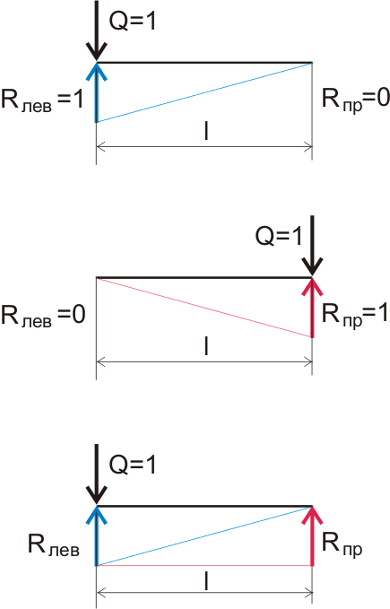
Figure 5.2. Graphical display of the change in the reactions of the supports depending on the distance of the load application.
If we have a load Q = 1 kgf applied on the left support, then the reaction on the left support (indicated in blue on the graph) will be Rlev = 1 kgf, and on the right support R pr = 0 kgf. If we combine these values, we get a right-angled triangle, in which the lower leg is the length of the beam, the second leg is the reaction on the support to which the load is applied, the hypotenuse in this case shows the change in the reaction of the support along the length of the beam, this line is called the line influence. If we depict the same thing for the reaction on the right support, then we will get exactly the same triangle, but for clarity we will depict it upside down. As a result, we got a regular rectangle of two right triangles, but in fact this is a magic rectangle (nomogram), which, without any special calculations, allows you to determine the reaction on any support, depending on the point of application of the load:
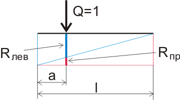
Figure 5.3. Graphic definition support reactions.
For example, the distance between the books is 20 cm. This means that the distance between the supports (the span of our beam) is 20 cm, and in the general case l . The length of the beam is measured along the axis X. If we apply a concentrated load at some distance from the left support, we denote it by the letter a, then the reaction value of the left support will be equal to the length of the segment drawn perpendicular to the long leg of the blue triangle, and the reaction value of the right support is the length of the segment drawn perpendicular to the long leg of the red triangle. In sum, they amount to one, since we took the load value equal to 1.
You can also determine the reaction of the supports by mathematical formulas describing the proportionality of right triangles: If the load is applied at a distance a from the support at overall length beams l , then the reaction on the right support will be:
R pr \u003d B \u003d Qa / l (4.1)
and the reaction on the left support will be:
R lion \u003d A \u003d Q (l - a) / l (4.2)
Of course, when calculating, everyone uses formulas, but the clarity of triangles will still come in handy for us.
When determining the reaction of supports from the action distributed load, first the resultant force is determined, i.e. the distributed load is reduced to a concentrated one, and then the reactions of the supports are determined depending on the point of application of the concentrated load. If the distributed load is evenly distributed and is applied along the entire length of the beam, then the reactions of the supports will be A = B = ql / 2. How to determine the support reactions in other cases, I hope, will become clear from the further description.
Bending moment equations, the third equation of static equilibrium of the system
If we put a 20 cm ruler on the books and press our finger in the middle, then the ruler will bend a certain distance, if we take a 40 cm ruler of the same section and from the same material, we will rest it on books stacked at a distance of 40 cm and apply it to the ruler exactly the same load, the distance that the ruler will bend will be greater, what's the matter? after all, neither the load, nor the material of the beam, nor the section of the beam have changed, only the length of the beam has changed.
Structural mechanics explains this miracle as follows: the forces acting on the beam are one thing, but the bending moment that occurs in the considered cross section under the action of a force is quite another.
We all remember Archimedes and his joy at the discovery of the lever principle, and so this principle operates everywhere, its essence boils down to the following: the larger the lever, the less force can be applied to do the same work.
In theoretical and structural mechanics, the concept of a shoulder of force is used, as a more correct one, thus it is believed that the internal stresses arising in the cross section of a beam under the action of a load are directly proportional to the shoulder of the acting force. And this means that the support reactions are the forces that are trying to bend the beam, while the fulcrum of the lever is our concentrated load. Such a change in the value of the moment depending on the arm of the force in mathematics is called a change in the value of the function depending on the variable X, thus it turns out that the value of the moment at any point of our beam can be described by the equation M = Px. The formula seems to be not complicated, but very important.
It turns out that in the section of the beam from the beginning to the point of application of the force Q, only one force acts on the beam - the reaction of the support R lion (for simplicity, the reactions on the supports are often indicated in capital letters, since there are many supports, it is customary to designate the leftmost support - " AND") and then the moment equation in this section will look like:
M = Ah(0≤ x< a) (6.1)
and in the section after the point of application of the force Q to the end of the beam, two forces act on the beam - the reaction of the support A and the force Q itself, and then the moment equation will look like this:
M \u003d Ah - Q (x - a)(a ≤ x< l) (6.2)
At point B on the right support of the beam, the moment equation will look like this:
M B \u003d Al - Q (l - a) + B (l - l)(x = l) (6.3)
These equations describe the static equilibrium of the system. For example, on articulated supports there is no bending moment and indeed, the solution of equation (6.1) at x = 0 gives us 0 and the solution of equation (6.3) at x = l gives us the same 0. Thus, equation (6.3) is the third equation of static equilibrium and can be written in the following form:
ΣM B \u003d Al - Q (l - a) \u003d 0 (6.4)
And also equations (6.1) and (6.2) allow you to determine the value of the moment at any point of the beam, and to be more precise, then at any considered cross section of the beam. Moreover, when solving these equations, we use the method of sections, which is discussed below, but for now let's consider the following illustrative example:
Beam on two hinged supports.
7.1. For a beam on which a concentrated load acts in the middle of the beam, it is easy to determine the bending moment at any point of the cross section on the left section of the beam: you need to multiply the reaction of one of the supports by the distance from this support to the point of application of the load (on the section of the beam from x = 0 to x=l/2). In mathematical terms, it will look like this:
M=(Q/2)x (7.1)
Since in this case the reaction of each of the supports is equal to half of the current load. The maximum value of the bending moment will also be in the middle, i.e. at a distance l / 2 from the beginning of the beam and will be:
M=(Q/2)(l/2) = Ql/4 (7.2)
The complete equation of moments, in the area where l/2< x < l , выглядит так:
∑M x \u003d (Q / 2) x - Q (x - l / 2)(7.3)
Under the action of the load and the reaction of the supports, a bending moment acts on the beam, and the value of this bending moment for each point, or rather, the cross section of the beam, is different. At the support points, the bending moment is 0, regardless of where the load is applied, since our supports are hinged. The maximum bending moment acts in one of the cross sections of the beam when a concentrated load is applied in the middle.
For clarity, when solving structural analysis problems, it is customary to build "epures" of the bending moment and acting forces, so that later it would be easier to determine the position of the cross section in which the maximum transverse or longitudinal force or bending moment acts. At its core, diagrams are graphs for functions described by the corresponding equations. For example, if the load is applied in the middle of the beam, then the diagrams will look like this:
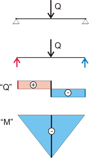
Figure 7.1. Plots of transverse forces and moments acting in the cross sections of the beam.
Plot "Q" displays the change in the forces acting on the beam, or rather, the change in shear stresses in the cross sections of the beam. So according to our diagram it can be seen that at the beginning of the beam, the value of the diagram changes sharply from 0 to Q/2 This is the support reaction. In the middle of the beam, where the force is applied Q, the value of the diagram changes sharply by the value " Q"and now is - Q/2, at the end of the beam, the second support reaction equal to Q/2, thus the plot value changes from - Q/2 on 0 . Signs "+" and "-" mean the direction of action of forces. If the force is directed upward (parallel to the axis at), then such a force is considered positive, if the force is directed downwards, then such a force is considered negative.
Diagram "M" displays the change in the bending moment acting on the beam, or rather, the change in normal stresses in the cross sections of the beam (about internal stresses, normal and tangential, we will talk a little lower). So according to our diagram it can be seen that at the beginning of the beam the bending moment is 0 and this is logical since the arm of the force, in this case the support reaction, is equal to zero, then the value of the bending moment increases in proportion to the change in the length of the arm of the force. In the middle of the beam, where the force is applied Q, on the "M" diagram, a fracture is observed, since another force comes into play - the applied concentrated load, which is 2 times greater in terms of the value of the support reaction.
Further, under the action of two oppositely directed, applied at different points and unequal forces, the value of the bending moment decreases and at the end of the beam on the right support, the value of the bending moment is again 0. From the diagram of bending moments, you can visually determine the value of the maximum bending moment in the cross section of the beam .
In this case, everything is simple and it would be quite possible to do without diagrams, but in the future, if you have to take into account the effect of different loads, including distributed ones, for a beam on several supports or with pinched ends, the presence of a correctly constructed bending moment diagram will help to accurately determine the position of the cross section of the beam (and not only the beam), in which the bending moment is maximum.
Even without long mathematical calculations, it can be seen that the closer the point of application of the load to the middle of the beam, the greater the value of the moment and the closer the point of application of the force to one of the supports, the closer the value of the moment to zero, and this is logical, the maximum moment occurs at the maximum shoulder of the force, therefore, when calculating a beam for dynamic moving concentrated loads (for example, people will walk on the beam or a car wheel will rest on the beam), there is no need to calculate the beam section for all load positions, it is enough to calculate the beam for the load applied in the weakest place - in the middle.
In this case, the "-" sign on the diagram of moments is nothing more than a convention. Whatever the direction of action of the moment, in the considered cross section there will always be both a stretched and a compressed zone. In this case, the diagram shows that the lower part of the section will be stretched. In general, the moment is considered positive if it tries to rotate the beam clockwise relative to the section point under consideration. Sometimes it is considered the opposite, but this is nothing more than a matter of convenience. In this case, the diagram of moments already shows whether the beam will bend up or down, without plotting the angles of rotation and deflections (we will talk about these diagrams a little later). In other words, it is much more important to understand where, as a result of the load, there will be a compressed, and where, a tension zone of the beam cross section, the sign of the moment is of secondary importance.
If we take the same ruler, stick one end of the ruler between books, or better between bricks, and leave the other end hanging, then we will get a model cantilever beam. The peculiarity of the cantilever beam is that it has only one support, and the rigid pinching does not allow the beam to rotate freely around this support. Since there is only one support, no matter where we apply a load to the beam, the reaction of the support will always be equal to the applied load. If, as in the case of a beam on hinged supports, we try to remove the support, replacing it with a reaction, then the equilibrium condition of the system will not be met, two equal in value, oppositely directed forces that do not lie on one straight line will rotate the beam around a certain point "o ":
Figure 8.1. The occurrence of a torque when equal forces are applied at different points.
As can be seen from figure 8.1 and it is clear from the description of the nature of the moment, than more distance between the points of application of forces, the greater the torque will be. In order to comply with the equilibrium condition of the system, we need to apply another torque to the beam, i.e. another pair of forces that will try to rotate the beam in the opposite direction.
The bending moment arising on the rigid support of the cantilever beam under the action of a concentrated load:
M = -Qx (8.1)
The bending moment that occurs on the rigid support of the cantilever beam under the action of a distributed load along the entire length of the beam:
M = -(ql)l/2 = -ql 2 /2 (8.2)
This can be shown in a diagram using symbol bending moment (known to us from the first part), but we are now interested in specifics. Since our beam has quite tangible height and width, it would be logical to apply these forces to the beam, or, to put it more precisely, to the cross section of the beam, and here even with the naked eye, it can be seen that the greater the height of the beam, the smaller forces can be applied to the very top and to the very bottom of the beam so that the moment value is the same:
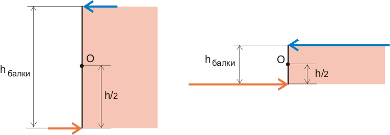
Figure 8.2. The increase in the value of forces with a decrease in the height of the beam at the same torque.
In this case, the upper force tries to stretch the beam, and the lower force tries to compress the beam. It seems that there is nothing complicated here, everything is quite simple and understandable, but in fact we have discovered the most important secret of the sopromat:
Bending moment acting on any building structure at some point, can be considered as a pair of forces acting on the cross section of the beam at that point.
Section method
This approach allows us, when solving problems, to consider not the entire beam, but only its part, replacing the missing part with a pair of forces acting on the cross section of the beam. So, for example, we could not consider the entire beam (figure 7.2), but only the right half, replacing the left half with a moment or a couple of forces.
And if in the considered cross section there are tangential stresses determined from the diagram of transverse forces, and (or) normal stresses determined from the diagram of normal forces, then in order for the cut-off part of the beam to be in equilibrium, we must apply all these loads to the considered transverse section.
This is the essence of the method of sections:
- When solving problems, we consider not the entire beam, but only its part cut off by the cross section.
- In order for this part to remain in a state of static equilibrium, we must apply external forces in the considered cross section.
- The internal stresses that arise in the considered cross section are the reaction of the material to the action of external forces.
Thus, by solving the equations listed above, we determine the values of the external bending moment, and now it's time to find out what the reaction of the material will be to this.
In this case, we have applied forces to the very top and to the very bottom of the beam (Figure 8.2), but we can apply these forces at any point in the cross section of the beam, the main thing is that the value of the external moment does not change. Concentrated forces can be replaced by a distributed load, which will create the same bending moment, and the value of the distributed load may vary depending on the height of the beam and can be graphically indicated as follows:
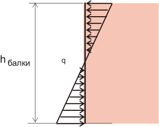
Figure 8.3. Change in the distributed load along the height of the beam.
Why the distribution of normal stresses along the height of the cross section of the beam has such a strange form, we will now find out.
Force reactions supports refers to elastic forces, and is always directed perpendicular to the surface. It opposes any force that causes the body to move perpendicular to the support. In order to calculate it, you need to identify and find out the numerical value of all the forces that act on a body standing on a support.
You will need
- - scales;
- - speedometer or radar;
- - goniometer.
Instruction
- Determine body weight using scales or in any other way. If the body is on a horizontal surface (and it does not matter whether it is moving or at rest), then the reaction force of the support is equal to the force of gravity acting on the body. In order to calculate it, multiply the mass of the body by the acceleration of gravity, which is equal to 9.81 m / s² N \u003d m g.
- When a body moves along an inclined plane directed at an angle to the horizon, the support reaction force is at an angle in gravity. At the same time, it compensates only for the component of gravity that acts perpendicular to the inclined plane. To calculate the reaction force of the support, use a goniometer to measure the angle at which the plane is located to the horizon. Calculate strength support reactions by multiplying the body mass by the free fall acceleration and the cosine of the angle at which the plane is to the horizon N=m g Cos(α).
- In the event that the body moves along the surface, which is a part of a circle with a radius R, for example, a bridge, a hillock, then the reaction force of the support takes into account the force acting in the direction from the center of the circle, with an acceleration equal to centripetal, acting on the body. To calculate the reaction force of the support at the highest point, subtract the ratio of the square of the speed to the radius of curvature of the trajectory from the acceleration of gravity.
- Multiply the resulting number by the mass of the moving body N=m (g-v²/R). Speed should be measured in meters per second and radius in meters. At a certain speed, the value of acceleration directed from the center of the circle can equal and even exceed the acceleration of free fall, at which point the adhesion of the body to the surface will disappear, therefore, for example, motorists need to clearly control the speed on such sections of the road.
- If the curvature is directed downwards and the body trajectory is concave, then calculate the reaction force of the support by adding the ratio of the square of the speed and the radius of curvature of the trajectory to the free fall acceleration, and multiply the result by the body mass N=m (g+v²/R).
- If the friction force and the friction coefficient are known, calculate the reaction force of the support by dividing the friction force by this coefficient N=Ftr/μ.