A lintel is a section of a wall located directly above a window, door or gate opening. Lintels are brick, arched, ordinary reinforced brick, steel, reinforced concrete. The most common precast concrete lintels. They consist of reinforced concrete standard bars and slabs.
Prefabricated jumpers are marked with the letters PR. If the jumpers, in addition to the weight of the masonry, carry the load from the ceiling, they are called carriers.
Jumpers, also called wire links, allow the designer to replace routing with a jumper component, often an essential component for successful single-sided board design. Early printed circuit boards were single sided. In order to successfully implement all connections, jumpers or wire links were often used to create another connection layer that could go through printed routing.
Jumper Display Control
Note the representation of the jumper with a curved connecting line between the two spacers. In the image, the jumper lines are shown in different colors, that is, because they inherit the color assigned to the network. The View menu includes a Jumpers submenu that allows you to control the display of jumper components. The Netlist pop-up menu also has a submenu.
On the plans, jumpers are marked according to the type PR-1, PR-2, etc. The lintel plan is drawn separately if the floor plan of the building is full of images, sizes and inscriptions and it is difficult to indicate the types of lintels on it, as well as when used in a building a large number jumper types.
On the plan of lintels, the contours of the main walls of the building are drawn at all levels where these lintels are arranged. The jumper is shown conditionally with one line above each opening and is marked (Fig. 10.8.1). On the same sheet, as a rule, a list of jumpers is placed. In fig. 10.8.2 shows the form and filling out the list of jumpers for civil buildings, and in fig. 10.8.3 - form and completion of the specification.
Jumpers and bill of materials
Jumpers are usually pieces of tinned copper wire bent to desired length. To support this, Jumpers can also be included in the schema to be included in the Bill of Materials. The Synchronizer and Reporting Engine has the following characteristics for jumper synchronization.
Suggested workflow for working with jumpers
Create a footprint for each jumper length that will be used. The lintels are typically designed to predetermined lengths, such as in 1 inch increments. As mentioned above, there are two conditions that make a jumper a jumper.
Create a Schematic Jumper Component
On the schematic side, you can.In addition, notes may be placed on this sheet and, if necessary, conventions. The contours of the walls of the building on the plan of the lintels are drawn with lines 0.3-0.4 mm thick, and the lintels themselves - with lines 0.6-0.8 mm thick. The jumper plan is drawn on a scale of 1:400, 1:800.
Attic or floor plan wooden beams are carried out to the same scale as the building plan. The plan shows the contours of the bearing walls, the location of the purlins and floor beams, their anchoring, the type of floor shields, the location of hatches, channels, etc. (Fig. 10.8.4).
On the floor plan of reinforced concrete, the contours of the external and internal walls of the building, girders, panels, as well as all openings, channels and hatches are shown. Floor plans are usually combined with prefabricated floor layouts. On the floor plan, a callout of individual units and parts is made or project sheets or albums of typical parts are indicated, where these elements are shown in detail. They indicate the brands of girders, panels, their number, width and distance from the edge of the panel to the plane of the wall, the amount of their support, as well as the mark of the bottom of the panel. Specifications for anchors, precast concrete elements, etc. are placed on the sheet of the installation plan for floors.

On fig. 10.8.5, a, 6 shows a floor panel with round voids of the PE brand (see Fig. 10.8.5, a), floor plan, details of supporting the panel on the wall and adjoining the panel to the wall: 1 - cement mortar; 2- concrete; 3- armature. MS - steel anchors that are attached to the mounting loop of the panel or slab and embedded in the wall masonry (see Fig. 10.8.5, b).
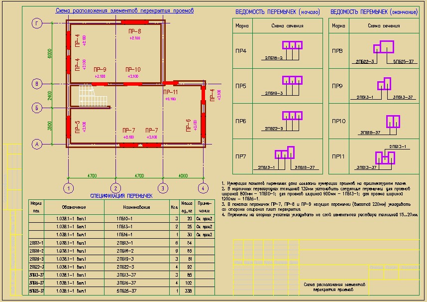
Now, according to the selected jumpers, we will execute the drawing "Layout of the elements of overlapping openings", and in the course of execution we will figure out what is being done in this drawing and why.
This article will be useful for those who want to learn how to make drawings, and for those who want to figure out what is shown on such drawings - how to read them.
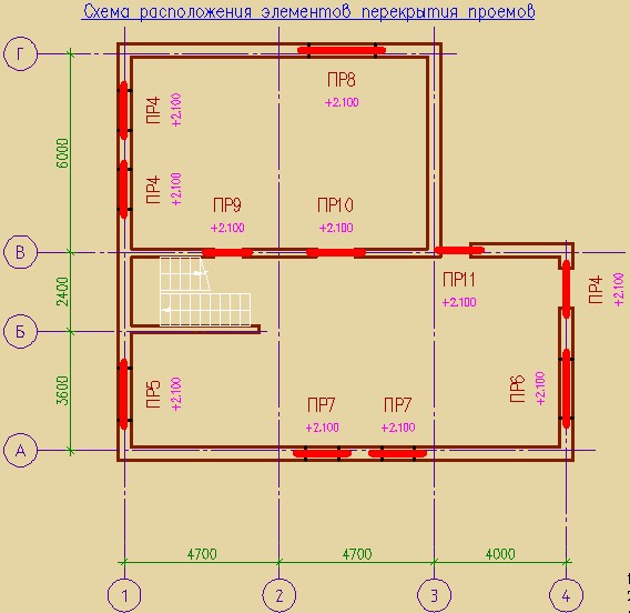
So, the first thing that should be shown in the drawing is a diagram. I'll start with the name "The layout of the elements of overlapping openings." Why is it so difficult? Why not just "Jumper Plan". We will leave plans to architecture. The designer's documentation contains diagrams - layout diagrams (see DSTU B A.2.4-7: 2009 "Rules for the implementation of architectural and construction working drawings", sections 5 and 6). Saying "foundation plan" or "floor plan" is not correct. And we, as competent designers, will call a spade a spade. We have openings that need to be covered with reinforced concrete elements (lintels) - and all this is shown in the diagram. Unusual, but logical.
There should be nothing superfluous on the diagram. Everything is clear and concise: the axis of the building; main dimensions between axles; walls with openings in them; schematic representation jumper packs in the form of a bold line (important - in bold); marking the jumper packs and marking the bottom of the jumper near each position (if desired). That's all that should be on the diagram. By the way, information on the mark of the bottom of the jumpers can be given in the form of a link to the facades and sections of the building.
In order not to clutter up the drawing, it does not show brick partitions with a thickness of 120 mm. These are not critical structures, each such opening is blocked by a single jumper, therefore instructions for overlapping these openings are given in text notes (they will be discussed below), and the jumpers themselves, of course, are still ordered in the specification. In addition, on big plans with an abundance of partitions on a scale of 1:100, it is very difficult to mark the jumpers. Therefore, such a solution greatly simplifies the life of the designer, and the builder cannot make mistakes in such a simple matter.
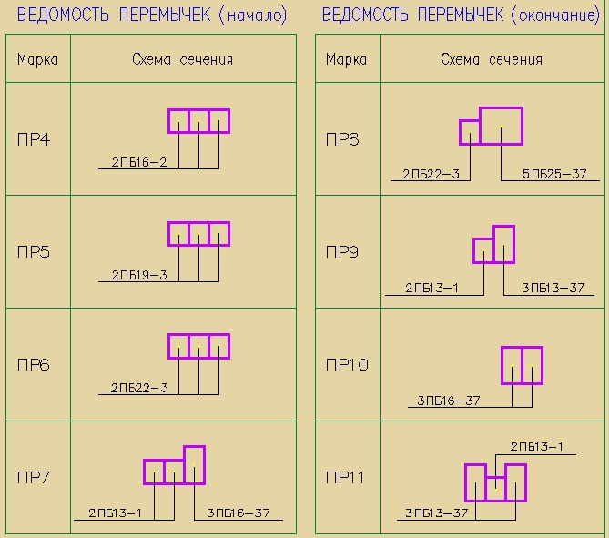
The next stage in the execution of the drawing is a list of jumpers (see DSTU B A.2.4-7: 2009 "Rules for the execution of architectural and construction working drawings", Appendix C). In this sheet, all packages of jumpers are drawn in a section, the brands of jumpers are given on the callouts - these can be either positions 1, 2, 3, or directly the names of the jumpers 2PB16-2, 2PB19-3, etc. Both marking options are allowed by the norms, the main thing is that the designations on the callout coincide with the designation in the column "Mark pos." in specification. I prefer to give the names of the jumpers on the callouts right away, so it's clearer, although there are more letters.
Additionally, in the list of jumpers, you can specify marks (if it is convenient), bindings to the coordination axes. You should not duplicate information: if the marks are indicated on the plan, then there is no need to talk about them in the list of jumpers and in the notes.
Packages from one jumper in partitions with a thickness of 120 mm should not be included in the list of jumpers. Enough note. Although, each designer is free to make an independent decision; but if you decide to depict jumpers in partitions in the list of jumpers, then you need to depict them on the diagram - with markings.
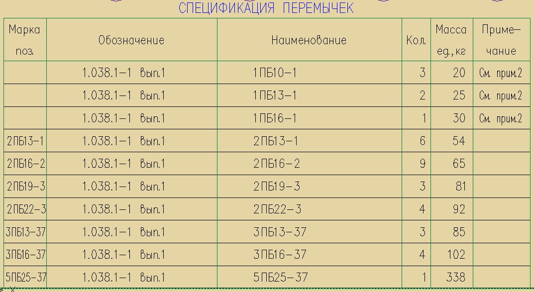
After the list of jumpers is framed, you need to collect data from it into a specification. For each brand (in our example, this is PR4-PR11), you need to calculate the number of jumpers and multiply by the number of openings with this brand. For example, jumper 2PB13-1 is found in jumper packages PR7 (two jumpers per package), PR9 (one per package) and PR11 (one per package); at the same time, we also have a different number of openings: PR7 - 2 openings, PR9 - one, PR11 - also one.
We calculate the number of 2PB13-1:
2*2 + 1*1 + 1*1 = 6pcs
Number of jumpers 6 pcs. must be entered in the column "Number." specifications.
And so on for each type of jumpers.
Also, do not forget to calculate and add jumpers in partitions (1PB10-1, 1PB13-1 and 1PB16-1) to the specification. At the same time, we do not assign position numbers (in the first column) to them, because they are not marked anywhere on the drawing. And in the last column of the specification we give a link to the note: “In brick partitions with a thickness of 120mm, install the following jumpers: for openings with a width of 800mm - 1PB10-1; for openings 900 mm wide - 1PB13-1; for an opening with a width of 1200 mm - 1PB16-1.
The second column of the specification gives a reference to the document according to which the jumper is to be made. In this case, this type series 1.031.1-1 issue 1. Instead of a series, you can also give a link to DSTU B V.2.6-55:2008 "Reinforced concrete lintels".
The third column gives the name of the jumper.
In the fourth (as already mentioned), the total number of jumpers is entered.
In the fifth - notes as necessary.
The last thing that should be on the drawing is technical requirements. In addition to those given in this example, it is necessary to add notes on the concrete grade for frost resistance - according to the climatic region (see clause 4.5 of DSTU B V.2.6-55:2008). It is also desirable to indicate which absolute mark corresponds to the relative one, taken in the project as zero (this information is important for builders).

As a result, we have such a drawing - clearly, precisely, nothing more. You can download it in pdf format
More articles on jumpers.