Kovka3D- a unique program designed for designing any metal structures in one plane or three-dimensional format. It was created by PulsarInvest and has extensive capabilities.
Beautiful models made using this software will decorate any design project during construction. Forged products will give your home an elegant look and unique style. Forged products, in addition to their excellent functional and quality characteristics, are today also a unique element of prestige. It is considered an attribute of everyday life of respectable and successful people who value style and reliability and have exquisite taste. Thanks to their compatibility with other materials, forged products fit harmoniously into any space and perfectly complement the interior.
In the application, structures are designed based on production capabilities, and materials for work are entered in accordance with GOSTs. Upon completion of the product design, almost all the information that is needed for the manufacture of the product, as well as the write-off of materials, and the formation of the cost of the order according to the cost parts will be displayed automatically.
A useful feature of the program is its catalog of materials, which contains the following materials: strip, circle, square, rectangular pipe, round pipe, square pipe, lightweight channel, channel without slope, channel with slope, economical channel, special channel, equilateral angle, unequal angle . In addition, cross-sections of materials of any proportions and sizes are available.
The program perfectly calculates costs and labor costs. You will also be able to create tech. maps, commercial offers on photos of the customer’s object. The advantages of the application include the presence of a library of finished products, decorative elements, as well as an editor for simple decorative elements. An excellent feature of the program is the ability to recalculate the cost of an order in case of changes in exchange rates or the cost of materials in the order register. To try all these features in action, you can download Kovka3D.
The program interface is Russian. The functionality of the application is very wide, as in another popular program for 3D visualization. Now, if you need to forge a fence, trellis, gate, balcony, etc., it's much easier to do it all. To do this, you should download Kovka3D for free.
The program will undoubtedly be useful to you, because good and high-quality 3D models are always in price. This is explained by the broad and rapid development of this industry in accordance with modern requirements and progress. Creating realistic visual models always requires professionalism, knowledge, skill and experience. With this application you will get an excellent opportunity to create models of insidious products with high efficiency. Any philosophy of a future metal product can be translated into 3D.
In a private house, hotel, office buildings, it is imperative to properly organize the space. The entrance and exit to the territory is very important, so a program for calculating gates will be needed by those who plan to build a detailed diagram of this structure. Gates can be different, differing in quality, materials, appearance.
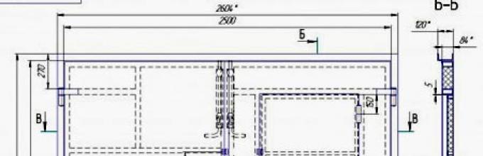
Drawing and design of sliding gates
Therefore, everyone should take the following steps before placing an order:
- Consider a pricing policy that suits all parameters;
- Decide how the gate should look;
- Decide on the company where the order will be made;
- Choose color solutions entrance shutters;
- Consider whether the design is suitable for the overall picture of the space.
What kind of gates can there be?
Gates differ in several indicators:
- The material from which they are made;
- Price;
- Complexity of design;
- Fastening elements;
- Construction design.
All these points are very important in the process of drawing up a diagram.
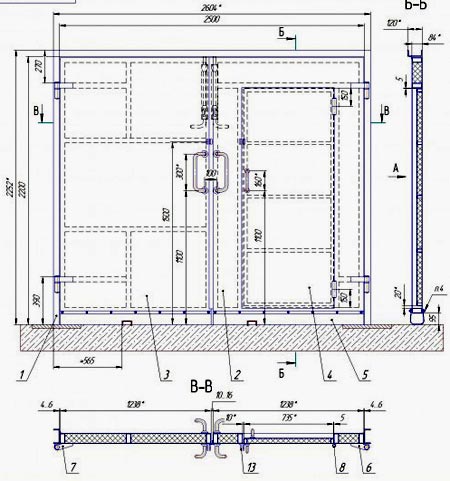 Diagram with dimensions of swing gates with a wicket
 The gates are also divided according to the following indicators:
- With a manual or automatic opening mechanism;
- WITH electronic lock or with mechanized;
- With straight lines or hand-forged.
What programs can you use to make calculations?
The gate calculation program will help:
- Calculate the required amount of materials needed for arranging the structure;
- Find out the amount of money for the purchase of raw materials or finished structures;
- Understand what height, strength, directionality the finished gate structure should be.
Calculations can be made in the following programs:
Kovka 3D
In this program you can make calculations of various. Gates are also one of them. By entering the required parameters, you can see all the necessary parts that are needed to build the gate. 
And also, you can understand how much money will be needed to carry out the mission. What data need to be entered:
- Desired height of the structure;
- Width;
- Gate control type;
- Material for manufacturing;
- Desired accessories;
- Metal structure design.
Read also
Creating a hedge of honeysuckle on the site
After entering the indicators, the system will provide detailed calculations of the cost, size, and design of the structure.
Sopromat
When designing gates, the program will help determine the number of required supporting structures(beams) for maximum stability of the structure. By entering the necessary data into the program, you can obtain detailed information about what support material is needed, in what quantity and what the pricing policy is.
 Calculation of gates in the Sopromat program
 Data that will need to be entered into the system:
- Gate height for a private house;
- Width;
- The thickness of the metal from which the product will be made.
All these indicators will help you clearly calculate what kind of beam system is needed to support a heavy structure. In addition to the above, there are also various calculation calculators, thanks to which you can clearly determine how much it will cost to erect a gate structure.
This is not really a program for calculating gates, it is more of a tool for determining the amount of materials needed.
How can a gate calculation program help?
Thanks to the fact that there is a program for calculating gates, every owner of real estate or private business can easily carry out the mission. 
This will help:
- Save cash on hiring specialists in the field of payments;
- Determine the exact quantity of materials and elements required for the gate;
- Understand how much financial resources will be needed to implement your plans;
- Select structures that are ideal in design and characteristics;
- See the gate before the moment of establishment;
- After making the calculations, immediately order services and materials on specialized websites that offer a program for independently selecting options.
1) Tekla Structures)
4D software system used in the construction industry for detailing steel and reinforced concrete structures. Software allows users to create 3models.
Tekla has a multi-user mode, very useful feature for working in large models. With this program you can create your own applications.
Import and export are carried out in the following formats: DWG, DXF, IFC, CIS/2, SDNF, DSTV, DGN and others.
2) Advance Steel
Software for 3D modeling and design of steel structures and automatic creation of working drawings. Can run on its own Platform.
The application supports all the basic functions of the AutoCAD program (attach points, grab points, copy, etc.). When running on its own CAD Platform, the application provides the same capabilities as AutoCAD. For the CAD Platform Advance Steel serves graphics engine object-oriented database. Compatibility is provided between different versions of Advance Steel.
Imports and exports to the following file formats:
GTC, DWG, IFC. 2x3, CIS/2, SDNF, PSS; KISS (“Keep it Simple, Steel”), DSTV, DXF.
3) AutoCAD
AutoCAD is a 2D and 3D design and drafting program created by Autodesk. AutoCAD program widely used in mechanical engineering, construction, architecture and other industries.
In AutoCAD, KMD drawings are developed in 2D and 3D. For 3D modeling, set specialized applications: Structural Detailing, RСAD-Steel.
AutoCAD Structural Detailing— a tool for the design and calculation of steel and reinforced concrete structures, supporting building information modeling technology. Basic objects are beams, columns, plates and reinforcing bars, etc.
RСAD-Steel- an AutoCAD-based application designed to perform working drawings at the KM and KMD stage. RCAD-Steel offers a full range of options for spatial modeling of steel structures and automatic generation of detail drawings and specifications. The process of drawing drawings in the program is fully automated. Drawings are based on the spatial model that the engineer creates using a specialized user interface and standard AutoCAD options, such as editing operations such as copying, moving, etc.
4) Compass 3D
Compass 3 is a computer-aided design program with the ability to prepare design and construction documentation in accordance with SPDS and ESKD standards.
There is a connection in the complex three-dimensional model and drawings with specifications, that is, with “proper” design, the specification can be obtained automatically; in addition, changes in the drawing or model will be transferred to the specification, and vice versa.
The program has different versions, for example, “KOMPAS-Stroitel” is designed to automate design work in the construction industry. It allows you to create working documentation according to SPDS standards.
5) Bocad-3D
Bocad-3D is one of the first 3D CAD programs for designing metal structures, which has been developing for more than 30 years.
This design system allows the designer to carry out very complex projects of buildings and structures in the shortest possible time and with great accuracy.
After creating a 3D model, position numbers are assigned, drawings and specifications are created automatically, which reduces the number of errors when obtaining the final result.
A large number of interfaces allow you to transfer data from the program to other applications (DXF-2D, DXF-3D, DWG, DBF, XML, PDMS, SDNF, SDS/2, etc.).
The NC-DSTV interface provides users with the ability to obtain files for CNC machines.
6) BricsCAD
BricsCAD is a commercial CAD system developed by the Belgian company Bricsys. Initially, the system was based on the IntelliCAD platform; in February 2010, it announced its withdrawal from the ITC consortium. This is one of the few CAD systems that supports Linux. It uses a library developed within the Open Design Alliance consortium for working with the DWG format.
7) CAD-PLAN ATHENA 2006
Program for the design of metal and facade structures ATHENA 2006. Along with numerous modifications and additions, we attach great importance to:
ATHENA configurator for designing 3D elements such as winter gardens, translucent roofs or facades - with material properties, design rules and production requirements.
12/06/2015 Introduction. Analytical methods for assessing the response of structures to external influences of various physical natures without full-scale modeling arose quite a long time ago. Emergence and development computer technology gave a new impetus to the improvement of numerical methods of analysis, which are today the main tool of calculations. Automated engineering analysis tools based on numerical methods have become an integral part of the product design process. To be successfully used, each calculation package must meet two requirements: . Implement the most efficient numerical algorithms; . Provide the user with a developed set of service functions for preparing initial data and processing calculation results. Depending on the degree of compliance with these criteria, all automation software is divided into light, medium and heavy. The degree of “severity” in this case is an indicator of power and efficiency. Let's consider the possibilities of “heavy” ones, i.e. the most powerful calculation systems. Ansys (ANSYS, Inc.) Ansys has been one of the leading heavy-duty finite element calculation systems for over 25 years. Beginning as a system for internal use at Westinghouse Electric, Ansys has expanded from its parent field, nuclear power, into all areas of the industry, gaining the trust of many thousands of users around the world. This success was achieved based on the following most important distinctive features: . Ansys is the only finite element system with such complete coverage of phenomena of various physical natures: strength, thermal physics, fluid dynamics and electromagnetism with the ability to solve related problems that combine all of these types; . The widest integration and two-way data exchange with all CAD / CAE / CAM systems; . Openness (i.e. modifiability and complementarity); . The highest efficiency/cost ratio; . Among the many finite element software packages, Ansys is the first and only one developed and certified according to the international standards ISO 9000 and ISO 9001; . Ansys provides the unique in completeness and most extensive content modern system help based on a hypertext presentation, accessed interactively online. The Ansys preprocessor allows you not only to create geometric models using your own means, but also to import ready-made ones created using CAD systems. It should be noted that the geometric model can subsequently be modified in any way, since during import the data is retranslated into the Ansys geometric format, and the part is not replaced by an “untouchable” finite element mesh. The user can remove unimportant small details, complete certain details, carry out thickening/thinning of the mesh and other important operations, without which the further solution may be completely incorrect or even unattainable. The construction of surfaces, solid and wireframe geometry and making changes is carried out using our own geometric modeler. As already noted, Ansys allows you to solve problems of strength, thermal physics, fluid dynamics, electromagnetism together with the calculation of fatigue characteristics and optimization procedures. A unified command system and a unified database completely eliminate the problems of integration and mutual exchange between these areas. Moreover, the program uses specialized finite elements that, in addition to movements and rotations at nodes, have degrees of freedom in temperature, voltage, etc., as well as switching the type of element, for example, electromagnetic to strength. Thanks to this, in the program unique capabilities for conducting related analysis have been implemented. Optimization of the design, thus, can be carried out taking into account the whole variety of physical influences on it. As a result of many years of cooperation between ANSYS Inc. and LSTC, the program includes the ANSYS/LS-DYNA module - a world-famous program for highly nonlinear calculations LS-DYNA, fully integrated into the Ansys environment. Combining in one software shell traditional methods of solving with matrix inversion and the mathematical apparatus of the LS-DYNA program, which uses an explicit integration method, allows you to switch from an implicit to an explicit solution method and vice versa. The described approach combines the advantages of both methods and makes it possible to numerically simulate the processes of forming materials, analyzing accidental collisions (for example, cars) and impacts under finite deformations, nonlinear behavior of the material and contact interaction large number tel. Using this transition function, problems of dynamic behavior of prestressed structures can be solved (birds caught in a prestressed engine turbine, seismic analysis of structures loaded, for example, with their own weight, etc.) and problems of studying the unloading of structures subjected to large deformations (elastic springing thin stamped sheet, etc.). LS-DYNA (Livermore Software Technologies Corp.) LS-DYNA, a multi-objective program using an explicit finite element method (FEM) formulation, is designed to analyze the nonlinear dynamic response of three-dimensional elastic structures. LS-DYNA was conceived as part of the US defense program and still is. A fully parallelized and vectorized highly efficient algorithm for solving nonlinear and fast-flowing processes, an automated process for solving contact problems, as well as many functions for verifying the resulting solution, allow engineers around the world to successfully solve the most complex impact, fracture and molding problems. The unique mathematical apparatus includes more than 25 contact interaction algorithms, more than 100 equations of state, which allows you to solve problems: . Nonlinear dynamics; . Thermal; . Destruction; . Development of cracks; . Contact; . Quasistatics; . Euler formulation of FEM; . Arbitrary Lagrangian-Eulerian behavior; . Acoustics in real time; . Multidisciplinary analysis: strength, thermal physics, acoustics; All of the above analytical tools allow us to simulate a wide range of real-life problems. Here are just a few applications of LS-DYNA's capabilities: . Impact resistance assessment (crash test): cars, aircraft, trains, ships; . Analysis of the dynamic strength of automotive components: body, bumpers, rims, steering columns, etc. when driving on an uneven surface; . Passenger safety assessment: interaction of airbag and virtual human model with seat belt simulation, airbag rupture, etc.; . Forming of metal, glass, plastics: rolling, extrusion, stamping, drawing, superplastic forming, cutting, profile rolling, casting, deep drawing, hydroforming (including large deformations) and multi-stage processes; . Bird resistance and turbine engine blade separation problems; . Interaction of liquid and gas flows with the structure; . Explosive load on products; . Penetration tasks (piercing an armor plate, introducing penetrators into the ground, etc. ); . Calculation of welded, riveted and bolted connections; . Biomedical Applications; . Modeling earthquakes. Eta/DYNAFORM (Engineering Technologies Associates) Eta/DYNAFORM is a specialized software package aimed at modeling sheet metal stamping processes and using the mathematical apparatus of the LS-DYNA program as its core. Pre- and post-processing DYNAFORM is built taking into account all the specific features of the technical process: it automates standard preparation operations design scheme and functions for evaluating and interpreting analysis results and is based on generally accepted terminology familiar to every process engineer. The program tools include: . Automatic grid generation; . Adaptive grids with animation of construction history; . Extensive library of industrial materials; . Automated tool positioning; . Involvement of the phenomena of loss of sheet stability - warping; . Calculation of tangential forces under clamps (braking ribs); . Calculation of elastic unloading of the product; . High-quality visualization of all results and animation; . Construction of the limiting “formability” diagram. ADAMS (Mechanical Dynamics, Inc.) Today, ADAMS is used in the automotive industry, aircraft manufacturing, astronautics, railway transport, general engineering, shipbuilding, robotics, instrumentation, biomechanics, and even in the leisure and entertainment industry. ADAMS provides users with the following capabilities: . Create a computer model of a system of rigid and deformable elements connected to each other by various connections and hinges; . Create a parameterized model based on the Parasolid solid modeling kernel, as well as exchange geometric models in IGES, STEP, DXF, DWG, STL formats; . Visualize the design model using powerful graphics tools; . Set forced displacements and movements of system elements and apply active external forces and moments; . Conduct static, dynamic and kinematic analysis of the system; . Visualize the movement of the system and record specified events; . Analyze the influence of variations in the parameters of structural elements on the behavior of the system (sensitivity analysis); . Optimize the product according to a given criterion; . Receive analysis results in a form convenient for evaluation and interpretation: graphs, tables, animation (high-quality animation, including specialized animation from the “driver’s point of view”, a camera flying around a moving product along a given trajectory, “following camera”, etc. ); . Perform two-way exchange of information with computer-aided design, finite element analysis, and animation software systems; . Customize the complex for typical tasks of a specific user; . Use specialized modules focused on specific areas of technology (automotive, railway); . Determine all parameters of the movement of the system, both from absolutely rigid and elastic links; calculate forces in connections and reactions in supports with full history changes over time, incoming forces on the controls; determine the mutual movement of components, movement and angles of rotation in hinges; conduct static and modal analysis and much more. Star-CD (Computational Dynamics) Star-CD was the first program in the world to include the so-called sliding grid procedure. Effective parallelization of the solution algorithm based on the application of the finite volume method, in combination with unique techniques for automated partitioning of the flow region, makes it possible to simulate problems of any degree of geometric complexity. Traditional areas of application for Star-CD are the following: . Transport; . Energy; . Chemical and processing; . General mechanical engineering; . Construction; . Electrical and Electronic; . Gas and oil production; Star-CD is a multi-purpose single CFD package that provides the user with the following capabilities for solving fluid and gas mechanics problems on all types of meshes: . Stationary and unsteady flows; . Laminar flows – Newtonian model and non-Newtonian fluids; . Turbulent flows (several of the most well-known models are used); . Compressible and incompressible (including near- and supersonic); . Heat transfer (convective, radiation, thermal conductivity taking into account solids ); . Mass transfer; . Chemical reactions; . Combustion of gaseous, liquid and solid fuels; . Distributed resistance (for example, in porous media, heat exchangers); . Multicomponent flows; . Multiphase flows - Lagrange model (dispersed gases - solid, gas - liquid, liquid - solid, liquid - liquid); . Multiphase flows – Euler model; . Free surfaces; Other options include: . Graphic and command input; . Specialized “novice”/“expert” operating modes, accompanied by interactive confirmations and hints; . Extensive set of meshing tools, including automated thickening; . Import of geometric models in STL, IGES and VDAFS formats; . Interfaces to CAD/CAE programs, including translation of finite element models, graphical presentation of results, etc.: Ansys, HEXAR, ICEM, I-DEAS, Nastran, Patran, Hypermech and SAMM; . Various means of visualization and processing of results (vector, color contour fills, isosurfaces, sections, particle tracing, animation, etc.); . Extrapolation of results on a mesh and surface of arbitrary type (used to output results to finite element packages); . Construction of graphs; Star-CD uses SAMM (Semi Automatic Meshing Methodology) developed by the engineering company Adapco as a preprocessor. SAMM provides the following features: . The use of mixed meshes from both four traditional (for example, hexagonal and tetrahedral) and unique cut prismatic elements; . The procedure for automatically “stitching” parameter fields in adjacent areas with non-coinciding breakdowns - arbitrary interface; . Automated adaptive thickening based on estimation of calculation error; . Dynamic distortion (adjustment) of the mesh to solve problems with variable boundary conditions (for example, piston engines); . Time-dependent, so-called sliding meshes using the “arbitrary interface” algorithm for blade machines, etc.; . Additional adaptive restructuring procedures (such as dynamic introduction and removal of elements, etc.); . Multiple rotating coordinate systems for modeling processes occurring in multi-stage turbine pumps, fans, etc.; . A means of accounting for cyclic symmetry or other types of periodicity for bladed and multistage machines in order to reduce the dimension of the problem. Star-CD uses highly efficient numerical algorithms. Typically, about 39 MB of memory is required for every 100 thousand cells. The Star-CD version for multiprocessor platforms Star-CD HPC provides an almost linear increase in counting speed (for example, on a 60-processor platform, a 57-fold acceleration was achieved). Robust numerical procedures provide the ability to solve extremely large problems (for example, to simulate the flow around an E-class car, specialists Mercedes Benz used a model of 10,000,000 elements. The solution was carried out on a 128-processor IBM SP2 computer. The memory request for the task was 6000 MB. CADfix (Finite Element Graghical Systems) The company was founded in 1970. The basis for the creation was the FAM finite element package of our own design. The main activity is the development of a universal tool for translating geometry and creating finite element models CADfix. CADfix is intended for users of professional CAD/CAE/CAM software systems who daily face data loss when translating models from one complex to another. The program is the only specialized product for restoring failed geometry and re-exporting data. Individual features of the internal representation of geometry in design systems, as well as the use of various systems as a “solid-state core”, lead to partial data loss when writing to neutral formats IGES, SAT, STL, etc., while the system often supports only such neutral import/export formats. The model obtained in this form is sometimes impossible to use at all. The more complex the geometry and the greater the desire to use a model that has already been built once, the more failures occur when trying to import it. Various kinds of incoherence, partial loss of surfaces, a whole forest of unnecessary auxiliary lines and uncut surfaces - this is just an incomplete list of everything that can simply poison the user’s life. All of the above problems can be solved only with the use of the CADfix package, which is based on the company’s 18 years of practical experience in this area. The program includes a unique set of tools for restoring geometric models, up to obtaining a solid model from an unrelated wireframe set of reference lines, as well as for modifying and exporting geometric files. One of the most important purposes of CADfix is also the creation of design models for finite element analysis - finishing the solid geometry to a state acceptable for partitioning and direct partitioning into finite elements. To characterize the capabilities of CADfix, here is a list of the most important of them: . Automatic scanning and visualization of detected problems with a prompt for resolution methods; . Automated iterative model reconstruction procedure; . Surface trimming; . Stitching within the limits of automatically determined or user-defined accuracy; . Parameterized “collapse” of lines and surfaces; . Breaking down solids into simpler components; . Availability of your own grid generator; . Application of boundary conditions for finite element analysis; . Export of reconstructed geometry in IGES, Parasolid, SAT, STL formats; . Direct transfer of reconstructed geometry to Ansys, Patran; . Export finite element mesh to Ansys, LS-DYNA, Nastran, etc. C-MOLD (Advanced CAE Technology, Inc.) The company was founded in 1986 in close cooperation with GE Plastics, GM Research, DuPont, Ohio State University and produces the leading software package C-MOLD in the field of numerical modeling of plastics processing processes. The FEA-based C-MOLD program is designed for computer simulation of processing processes for all types of plastics. The program implements modeling of many technological processes, in particular: casting, thermoplastics under pressure, gas injection molding, two-component casting processes, pneumatic vacuum molding taking into account the phenomena of shrinkage and warping and many others, and in addition, calculation of material and product parameters at all stages processing with the ability to optimize both the injection mold (position, shape of the gates, etc.) and the product itself. COMET/Acoustics (Automated Analysis Co) AAS was founded on January 12, 1983. Now AAS, an engineering and consulting firm that is one of the distributors of ANSYS and some other programs in the United States, is also developing software and carrying out calculations for industrial orders. ACC cooperates with leading CAD/CAE/CAM manufacturers. The COMET/Acoustics software package allows developers to calculate its acoustic properties and optimize the design even at the product design stage. It is used in the automotive, light, aerospace industries, mechanical engineering, and scientific research. The complex includes two specialized modules: . SAFE (Structural Acoustic Foam Engineering), which allows you to analyze the process of acoustic energy passing through foam-like materials; . SAOpt (Structural Acoustic Optimization), which allows you to simultaneously optimize the design of a structure and its acoustic characteristics without tedious iterative calculations and continuous switching from acoustic to strength analysis. ProCAST(UES, CALCOM) According to research conducted by NASA experts, ProCAST is recognized as the most powerful and correct program for calculating foundry processes. ProCAST allows the design engineer to calculate and visualize in three dimensions the process of flow and solidification of metal in a mold, predict microstructure, the occurrence of cavities, porosity, optimize the position of gates, minimize residual stresses, control the heat balance of the casting-mold system, etc. Based on the calculation results, the optimal locations of the vent (gas outlet), refrigerator, and injection channels can be obtained. ProCAST is built according to a modular design: . Thermal analysis; . Flow analysis; . Grid generator; . Radiation analysis; . Strength analysis; . Modeling of microstructures; . Inversion modeling module; . Electromagnetic analysis. The MechCAST module produces automated generation of three-dimensional finite element meshes based on models imported from CAD systems. MechCAST works with the following graphic formats: IGES, STL, Unigraphics Parasolids, and also has a direct two-way data exchange interface with Pro/Engineering, Unigraphics and finite element packages Ansys, I-DEAS, Patran, Hypermesh, Ifem, Gfem, Aries, Fam . Pro/Engineer Pro/MESH, Pro/FEM-POST and Pro/SURFACE – Pro/Engineer modules for finite element strength analysis. Pro/MESH provides the designer with the ability to create finite element meshes for models produced in Pro/Engineer. Thin-walled and solid-state objects can be automatically modeled, broken down and exported to separate programs for further analysis. Pro/MESH is an additional module of the Pro/Engineer family. Pro/FEM-POST provides a complete set of post-processor capabilities for analyzing finite element analysis (FEM) results and gives users the ability to display analysis results in the Pro/Engineer environment. Pro/FEM-POST simplifies the end-to-end design/analysis process in an integrated environment that combines the full associativity of Pro/Engineer with the capabilities of a modern post processor to analyze finite element results. User-friendly interface ensures early design and optimization decisions are validated