The frame house according to its own design is represented by the main and auxiliary nodes. During the construction of the building, it is important to pay increased attention to them.
Incorrect docking and fastening of elements that do not meet the standards can lead to disastrous consequences, since it is life-threatening to live in such a house. At some unexpected moment, it will simply fall apart “into spare parts”.
The main nodes are represented by floor systems, roof structures and wall systems. In turn, they are subdivided into sub-nodes. Each of them will be discussed below.
Element represented as a bottom strap knot
The knot of the lower strapping, is called the place of attachment to the foundation of the strapping bars. To carry out the docking process, foundation bolts, clamps or other methods are used. Before laying the beams, the joint is waterproofed.
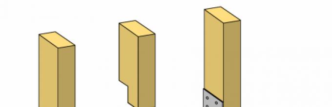
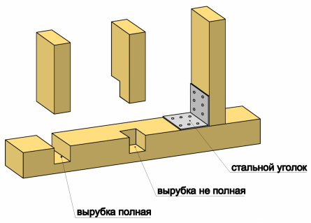
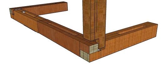
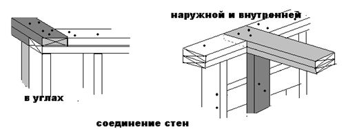
Docking corner element designed for strapping bars
As another structural unit of the lower trim of a frame-type house, there is a place at the corners where the beams are joined to each other. To do this, use the method "in the paw" or "half a tree". Metal corners or bolts are used for the purpose of a tight connection.
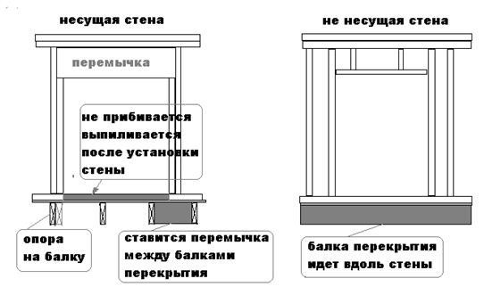
Implementation of the installation of floors of beams of floor and ceiling type
Laying of floor beams is carried out with the necessary step. The place for their emphasis is the strapping beam. Installation of ceiling beams is carried out in a similar way.
Installation of vertical racks
 The frame house begins to be erected with the installation of corner vertical racks. Then they are already engaged in the construction of intermediate elements. Here it is worth dwelling on the presence of several nodes at once. These are the places where the vertical posts are joined in the corners with the strapping, both upper and lower, and those places where the posts and strapping beams are connected to each other. Vertical racks in the corners are fixed with grooves and metal corners as additional elements. Intermediate racks are fixed in the same way.
Nodal element of the upper harness
The fastening of the bars of the upper trim is carried out in the same way as the bars of the lower. Docking is carried out in the corners and with frame racks.
Application of additional "links"
In order to give strength to the frame, diagonal and vertical supports reinforcing it are used. Although it is quite rare to come across such a solution. Most often, OSB-plates are used for reinforcement, with the help of which the frame is sheathed. This is quite enough.
Nodal elements of the truss system
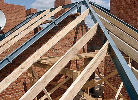 The concept of a rafter system implies the presence of numerous nodes. There are rafter support nodes, the location of which is the ridge run, you can also find rafter support nodes, which are located on the beam of the upper trim. You can encounter types of nodes in which the rafter legs are connected to the crossbar, or other struts, or with the bars of the counter-lattice. The rafter system sometimes implies the presence of a node in which the crate and counter-batten are connected to each other.
The connection of the rafter legs at the ridge to each other can be done end-to-end or overlap. The rafters can be attached to the Mauerlat by cutting them out. Crossbars and other supports are presented in the form of boards or bars. The installation of the bars of the counter-lattice is carried out using a similar step with the step of the rafter legs on top of them. In order to make a solid or sparse crate, a board is used, and the type of construction is directly influenced by the type of used roofing. When planning the construction of a frame-type house, you need to familiarize yourself with the device frame house, with all the nuances of its construction in order to prevent problems that arise unexpectedly during the process of building a house. Everyone can build a frame house with their own hands.
What are the mistakes made in the process of building a frame house?
If you have made a decision related to the construction of a frame house with your own hands, then you should not make mistakes. The most common of them are presented below.
The use of poor quality wood
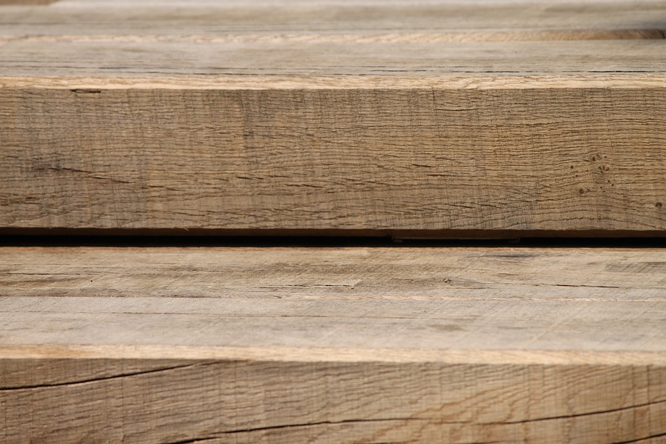 The construction of a frame house is carried out using insufficiently dried wood, and this is a significant mistake. When dried, the tree changes its shape. As a result, the house may squint, the nails will be partially turned out. Accordingly, damage will be done to the house, insulation and finishing material. Rapid drying of wood is unacceptable. This process should take several days. If you ignore compliance with the requirements, then a split or bending of the board and timber will occur. Immediately after the drying process, the wood must be treated with compounds that protect the house from fire and rodents.
Incorrect frame reinforcement
 The frame acts as the main structure of the house. Therefore, the process of its construction must be approached with maximum responsibility. Vertical racks deserve special attention, since they tend to have little resistance to lateral loads. In order to eliminate the problem, it is important to reinforce the frame using diagonal ties. This process is carried out in several ways. You can use spacers, sheathe the house with plywood, or use OSB sheets for this. Struts can be made from above and below. The place of emphasis for one of the ends should be a vertical stand, and for the other - the strapping bars. The sheathing of the frame is most often performed using plywood or OSB boards for this. They must be at least ten millimeters thick. The moment of high-quality fastening of the plates on the frame with the help of self-tapping screws, the diameter of which is four centimeters, is important.
When there is no vapor and waterproofing
Insulation can be seriously damaged in the absence of hydro and vapor barrier. Because wet exposure is fraught with its deformation, as a result of which it will not be able to perform its functions. Wood also suffers from moisture. Damp, it begins to deform, and bugs start up in it.
If there is no foundation waterproofing
From the foundation, the beam of the lower strapping must be protected by laying a layer of waterproofing. Otherwise, it will be affected by groundwater, and it will undergo a process of decay. It will have to be changed after a few years, and this is an expensive and complicated operation.
Failure to follow the step during the installation of vertical racks
The width of the insulation boards reaches 0.6 meters. Accordingly, between the racks of the frame frame, there must be a step that is 59-60 centimeters.
Incorrect fastening of uprights
It is undesirable to use only self-tapping screws for the purpose of fastening the frame racks. The best option there will be an additional drive in of several nails to each other at an angle from two sides. All joints should be worked out with the highest quality. Although the list of the above errors is far from complete. When using frame technology during the construction of houses, many more mistakes are made. In order to prevent their admission, you need to contact a trusted company that has been doing this for a long time in your city.
Everyone who decides to build a house is puzzled by the question related to the cost of work. By correctly compiling an estimate for a frame house, you can give the most accurate answer to this question. The estimate includes two parts, presented construction work and installation of utilities. Shipping costs are taken into account together with the prices of materials.
All walls must be framed.
The dimensions of the uprights and the distances between them must be consistent with the data .
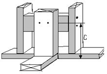
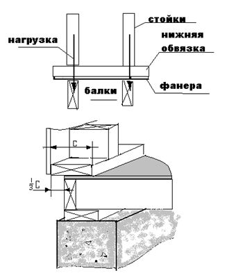
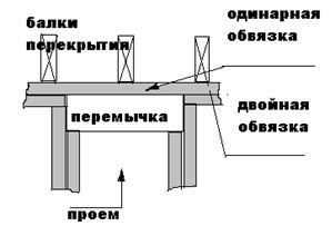
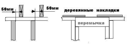
Bearing racks must be additionally reinforced with a coating (plywood, chipboard, drywall, etc.) or oblique struts. Racks should be located at right angles to the plane of the wall Racks are allowed to be placed parallel to the wall on the gable of the roof, which closes the unused room or in non-load-bearing internal partitions, subject to the restrictions defined in. Racks supporting a load consisting only of an unused attic can be located parallel to the wall if: the front side of the racks is reinforced with a coating. The portion of the roof supported by a wall with this arrangement of studs must not exceed 2.1 m in width. Racks should go to the entire height of the floor, with the exception of places where openings of windows, doors, etc. are located. Racks should not be connected from several parts. Wall corners and intersections must be designed and constructed to provide sufficient support to the edges of the outer and inner covering. In the frame of the walls in the outer corners there must be at least two racks. Where the vertical edges of the inner coating are reinforced with lintels that serve to fasten the inner wall to the outer one, the lintels are placed at a distance C that provides reliable support for the inner coating. (See chapter ). The thickness of the boards for tying the walls must be at least 38 mm. The width must be equal to the width of the supporting racks of the frame (with the exception of non-load-bearing walls). In load-bearing walls where the vertical studs coincide with the floor beams vertically and directionally, the bottom framing board can be 19 mm thick. The bottom strapping board must be in all cases. The lower strapping board in the outer walls should not protrude more than 1/3 of the strapping width above the support. The top harness must always consist of two boards, with the exception of: There is an opening in the wall for a window or door, and a lintel is installed above it, which forms one knot with the dressing of the wall; The upper strapping board can be used as a single one in the section of the bearing wall, where the load from the ceiling or rafters (trusses), the roof is transferred no further than 50 mm. from vertical wall studs on one side. In all internal non-bearing walls. The upper trim may be completely absent above the openings with lintels, if the connection between the wall and the lintel is made with steel plates (not rusting or treated with anticorrosive) with a size of at least 75X150X0.91mm or wooden slips 19X89X300mm. Wooden studs must be nailed to each section of the wall with at least three nails of 63 mm or more. 16 The joints of the boards in the upper harness should be above the centers of the vertical posts and go among themselves in a checkerboard pattern at a distance of at least a step of the vertical posts. Between themselves, the boards of the upper strapping should break through as follows: at the ends of the boards - two nails; over each rack one nail in a checkerboard pattern. At the joints of the walls, the joints of the upper trim should overlap with the bottom board of the upper trim of the other wall. Bundles are equivalent for tying corners and joints in walls with one top tie board. Double racks are installed on the sides of all openings. The internal posts are installed from the bottom trim to the lintel above the opening, the outer ones go from the top to the bottom trim. Single studs on the sides of openings are allowed in non-load-bearing internal walls (only in houses where a high degree of fire resistance is not required) In the window openings, a window sill or a supporting board of the window opening is installed. Vertical posts go from the bottom trim to the window sill board. They are installed according to the marking of the wall. On the sides of the opening, racks are additionally installed under the window sill. Lintels above door openings in non-bearing walls must be made of material no thinner than 38 mm and equal in width to the width of the vertical posts. This rule is mandatory for non-load-bearing walls intended as fire barriers. I think that it is better to make such openings as in load-bearing walls. Openings in load-bearing walls must be assembled with lintels (at least two) in order to transfer the load. The lintels must be fastened together with nails in two rows (nail length not less than 82 mm), with the distance between pairs of nails not less than 450 mm. If the jumpers do not reach the upper trim, then racks are installed between them (strictly according to the wall markings). Both jumper boards are interconnected by gaskets (plywood, board, etc.). On walls assembled from 140 mm boards, it is better to tie them from below with a suitable board of the same width. The dimensions of the cross-sections of the boards for the lintels in the walls depend on the span of the given opening. It is important to remember when designing and building construction that double lintels are used in walls where the section of the racks is 38X89 or more. It is possible to use jumpers 89 mm thick consisting of one piece of wood. In walls assembled from boards with a section of 38X64 mm, lintels can also be made from a single piece of wood 64 mm thick or from two boards 38 and 19 mm connected with nails 63 mm through 450 mm. In this case, the jumpers should be 50 mm wider than in and not exceed 2.4 m in length.


In wall openings exceeding the values, it is necessary to assemble beams consisting of three or more boards with a thickness of 38 mm, installed on the edge.

External walls with outside should be sheathed. If reinforcing sheathing is not performed, then the walls must be reinforced with diagonal braces. It can be boards, steel or aluminum profiles.
Can be used for exterior wall cladding various materials(look ). So far, it is best to use plywood for us. You can use boards, but it's already expensive. The thickness of the sheathing depends on the selected distance between the uprights.
Fastening of sheathing sheets can be vertical and horizontal. Sheathing boards are mounted horizontally or at an angle of 45 degrees.
A gap of 2 - 3 mm is left between the sheathing sheets.
It is better to use nails that are not subject to corrosion, or suitably treated, for fastening the sheathing.
Sheathing sheets are attached to the frame with nails:
- along the edges of the sheet no more than through - 150 mm;
- to the racks in the middle of the sheet - 300 mm;
- along the edges of wall openings - 150 mm;
- from the edges of the sheathing, nails are driven in at a distance of 10 mm

Nails for assembling the frame of the walls and the procedure for their use.
Consider the most important nodes of the wall frame:
To the top and bottom strapping boards, the posts are nailed with at least 2 nails on each side. The minimum size of nails is 82 mm. For us, the most suitable nails are 90 mm. it minimum size. You can also take a larger size.
 -
-
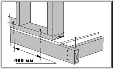
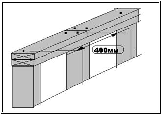
At putting the walls in place, the bottom trim is attached to the floor platform at least 400 mm apart. A 90 mm nail, through the plywood of the floor sheathing, must enter the floor frame.
- The second board of the upper trim is nailed at the ends with 2 nails, not less than 82 mm.
Along the entire length, the second strapping board is nailed with nails of at least 76 mm, after 600 mm no more in a checkerboard pattern. In practice, a second board of top trim is nailed over each upright.
AT doorway, after sawing out the bottom strapping board, two 82 mm nails are hammered in so that they pass through the bottom strapping, plywood and enter the floor frame.
Lintels over openings in the walls are nailed to the wall frame posts with at least three nails (each lintel board). Nails 82 mm or larger are used.
Double racks used to create a frame opening break through each other through 400 mm (at least). 
From the edge of the board, nails should be hammered in at least 20 - 25 mm.
The second board of the upper trim, when overlapping on another wall, is nailed with at least 3 nails.
If the wall structure does not provide for a second upper framing board, then a metal plate 19X89X300 mm is used to connect the upper framing of the walls. It is fastened - three nails in each wally.

PRACTICAL ADVICE FOR WALL DESIGN.
1. Usually, in low-rise construction, the thickness of the outer walls is selected from the conditions of thermal resistance of the enclosing surface. In our construction, it is easier and cheaper to proceed from the strength conditions of the wall frame. Why:
market building materials is developing rapidly. While the house is being designed, the frame is being built, a heater with the best qualities may appear.
2. It must be remembered that the maximum number of floors when using this technology is three or two floors plus an attic.
3. For internal walls, a board with a section of 38X89 mm is sufficient. Near sanitary facilities, in many cases, where communications for sewerage will pass, it is more convenient to use boards 38X140 mm.
All frame house structures consist of the following parts and elements - lower and upper trim, vertical stand, slopes, basement and interfloor ceilings, window and door openings. The sequence of assembly and installation of a wooden frame house will depend on the applied engineering solutions.
The most popular are the so-called platform frames.
 Their name is explained by the fact that before the construction and, first of all, a basement floor is built, followed by laying a rough one. Fragments and structural elements of a frame house are assembled into frames on a finished platform, then they are assembled and installed to the ceiling on top of the installed subfloor.
After that, the operations are repeated, interfloor ceilings are fixed, on which the walls of the next floor are installed.
The advantages of this design frame house are perfected special technology and ease of execution and installation of work. The presence of a flat and smooth base greatly facilitates the layout and subsequent installation of all elements, and also allows you to assemble all the walls of the frame with maximum accuracy and reliable quality.
The disadvantages of the platform design is that after laying and installing subfloor sheets, it is not recommended to let it get wet. And in conditions of cloudy and rainy weather, it is imperative to provide protective measures for floors from rain.
Another disadvantage is the repair of platform-type frame ceilings. The walls of such a frame stand directly on the floor beams, and this makes it difficult to replace the main beams, without serious and thoughtful intervention in the rest of the details and elements of the entire structure.
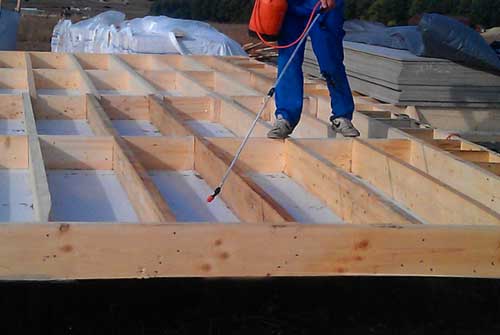
Floor treatment with antiseptic impregnation
Such a problem will not be relevant if all the details and structural elements are well and efficiently processed, and they will be used in normal humidity conditions. Life time ground floor and its structures can be significantly reduced due to poorly ventilated underground, constant waterlogging and poor biosecurity. In connection with such conditions, during construction, access to the underground and basement floors for periodic technical inspection of structures should be provided.
Basement design options
There are many other types and options for the design and its basement. One of these is the installation of the ceiling after the installation of the wall frame. Beams are placed on top of the horizontal wall board of the frame. This option will allow you to replace floor beams if necessary.
- The disadvantage of this scheme is that in the absence of a smooth and even base, the assembly of the walls of the entire frame takes place under complicated conditions. In addition, it will be difficult to trim the slabs and subfloor insulation in the area of the joints of the ceiling and walls.
- The second version of the basement floor is that the installation is in the form of a separate assembled box inside the entire perimeter of the walls. Thanks to this, the design of the wall of the frame house and its ceiling will be completely independent of each other. Such a design would be possible if large enough. It is this option that will allow you to move the walls of the house to the outer edge, and install floor beams on the inside.
Installation of walls from the side of the foundation platform
This method is interesting in that, with better maintainability, it perfectly retains all the advantages of the platform. On the foundation, a floor box is initially erected, and after that all the walls are already assembled on it. The main difference is that after the final assembly, the walls are placed side by side to each other, and not placed directly on the ceiling. The disadvantage of this design will be the use of a wider one compared to the options that we considered earlier. This will lead to an increase in the cost of all materials for the foundation and an increase in its cost.
It is possible to build frame houses on almost any type of foundation.. The most common solution involves using or . In this case, the tops of all the pillars are combined with a special thick strapping, on which the frame is attached. Before installing the frame, a layer of roll is attached to the foundation.
Types of connecting elements and nodes of a frame house
During construction and repair, it is often necessary to connect elements and parts into units and special structures. Connections of wooden elements and structural parts are commonly called landings.
Joints in timber structures can be defined by five types of fits: tight, tight, sliding, loose, and very loose fits.
Knots of connections of a frame house
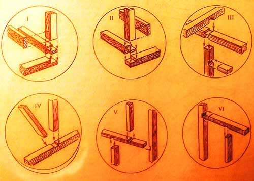
Nodes are parts wooden structures at the junctions of elements and parts. Connections of wooden structures can be divided into the following types: end and side, corner and T-shaped, cross-shaped and L-shaped, as well as box corner connections.
Joiner connections can have more than 200 options. We will consider only those connections that joiners and carpenters use in their work.
End connection of parts- this is a connection of elements and parts along the length, when one of the elements is a continuation of the other. These joints can be smooth, serrated and spiked. Additionally, they can be fixed with glue, screws or special pads.
End connections of the horizontal type withstand huge loads of compression, bending and tension.
It is customary for all lumber to grow in length, thus forming vertical and horizontal jagged joints at their ends. These connections are not under pressure during the entire gluing process.
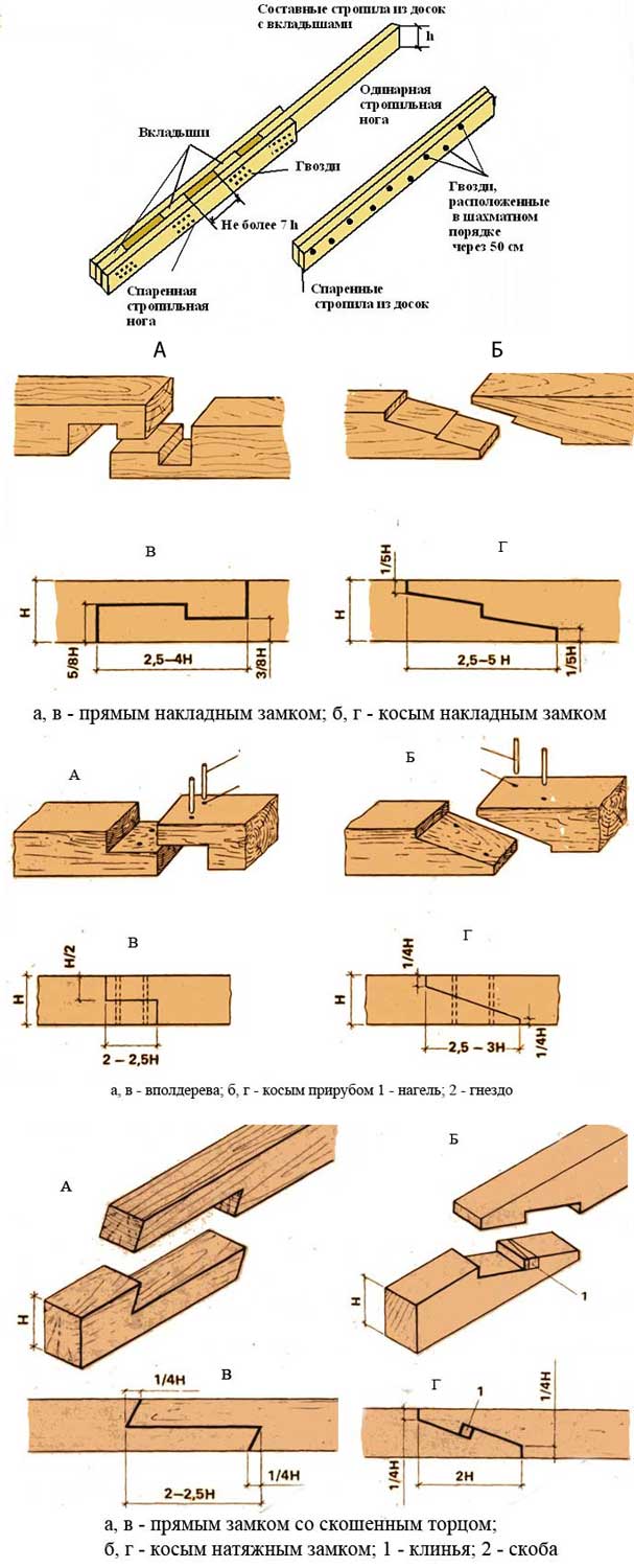
Lumber connection. Types of spikes
Connections for wooden structures are made carefully and reliably, in accordance with the three main accuracy classes.
The first class is intended for special measuring tools of high quality, the second class is for products and parts of furniture production, and the third is for building parts, inventory for Agriculture And so on.
Lateral connections with an edge, several boards or slats are called rallying. These connections are used in the construction of floors, gates, etc. With the ceilings of a frame house, the upper boards will overlap the lower ones by 1/4 of their width. External walls are usually sheathed with an overlap of horizontal stacked boards. The top board should overlap the bottom board by 1/4 of its width, this will ensure the removal of precipitation.
Connecting the ends of a part to the middle part of another part forms a T-joint. This connection has a huge number of mounting options. Such connections (usually called knitting) are used when pairing the log of all ceilings and interior partitions with the strapping of a frame house.
The connection of elements and parts at a right or oblique angle is called a cruciform connection. This connection has one or more grooves. Cruciform connections are commonly used in farm designs.
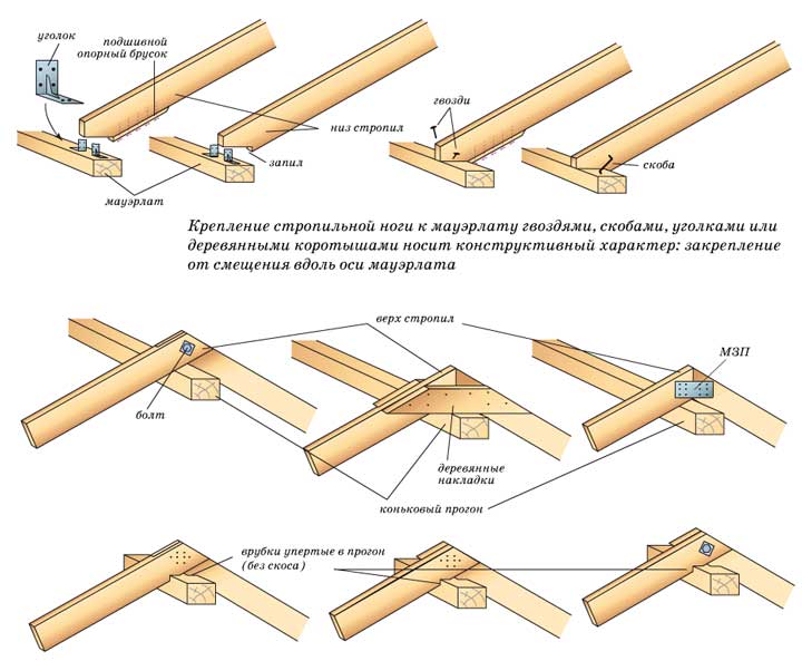
Connections for roof structure
The main and most common connections in a frame house easier and more reliable to do with special fasteners. Each of them has its own fasteners, which ensure the strength and stability of the entire structure. It is easy to use and allows you to abandon such laborious connections as a half-tree tie-in or various "locks".
Connecting fasteners for assembling frame wooden building structures has been used for a long time: tightening brackets, bolts and clamps. Very often used in construction frame houses. Today it has become more diverse and perfect. Fasteners not only simplify and speed up the assembly of building structures, but also make them stronger and more stable. Fasteners are most effectively used in the construction of prefabricated frame houses. Connecting fasteners for the assembly of building wooden structures are too diverse to be described in one article. Therefore, using the example of a frame house, we will consider only a part of the fasteners, but the most used and mass-produced.
Connecting fastener made of cold-rolled steel sheet with a thickness of 2.0 - 4.0 mm, in the form of perforated (with holes) plates, corners, holders, supports for beams, connectors (plates with needle spikes - connectors), as well as shoes for bearing racks and columns mounted directly on the foundation. Depending on the purpose (dimensions of the connected parts and the loads transferred to them), each type of such fasteners is presented in several versions: in size, perforation configuration (holes) and even with additional elements(ribs) of increased rigidity.
Fastener perforation regulates the thickness of nails and tie bolts, as well as their number: on the one hand, they are enough to securely fix the connection, on the other hand, wood cracking does not occur. Such fasteners can have various coatings that protect them from corrosion: zinc, primer or polymer powder paint. Part of the connecting fastener is also used for repair work (for example, a corner when constructing the frame of internal partitions). Therefore, when choosing such fasteners (standard sizes, metal thickness, design option, perforation, stiffeners and protective coating), one should imagine what loads it will experience during operation.
Connecting fasteners have a number of undeniable advantages over classical connections in the construction of low-rise wooden houses and, first of all, prefabricated-frame, in which you have to make a lot of different nodal connections.
Firstly, there is no need to perform time-consuming and skill-intensive classic connections such as half-timber tie-ins or long locks. There is no splitting of wooden structures due to an excessively large number and sizes of nails and bolts: the normalized perforation of fasteners (holes) does not allow the use of too thick nails and driving them close to the edge of the bar.
Secondly, the classic tie-in leads to a decrease in the strength of the timber due to a decrease in its cross section at the joints (wood sampling). Steel connecting fasteners, on the contrary, create additional reinforcement of the structure of the nodes.
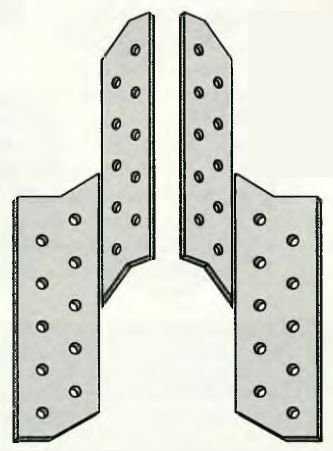
: used in butt joints where tensile loads are applied, such as when splicing a beam for tightening or making roof trusses.
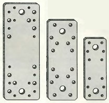
Mounting plates are used in connections that experience tensile loads. They are applied to the connection on both sides and pulled together: with bolts - 2 holes with a diameter of 11 mm and with nails - the remaining holes with a diameter of 7.5, 5 and 4.5 mm. The dimensions of the holes determine the diameter of the bolts and nails used: their task is to ensure the necessary strength of the connection, preventing splitting of the wood.
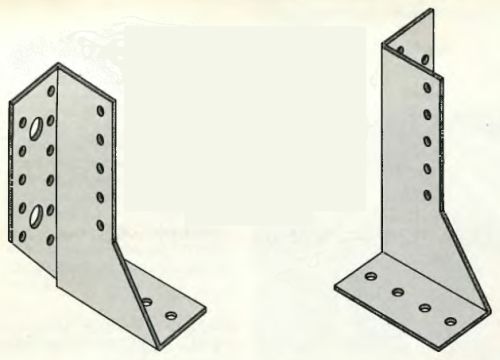
: used in various corner joints (walls, racks with a supporting frame, tie beams, roof rafters, etc.). An angle with a stiffener has a higher resistance to bending loads.
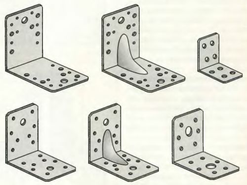
Mounting angles are used for angular connection between walls or the upper tie bar with a roof truss. They are presented in various sizes and several designs, including those reinforced with a stiffener. The corners are applied to the connection from two sides and tightened: with bolts - 2 holes with a diameter of 11 mm and with nails - the remaining holes with a diameter of 7.5, 5 and 4.5 mm. Bolts for fixing are used only in particularly strong connections.

Installation of beams attic floor or roof rafters using mounting brackets. Fastener perforation ensures the optimal number, thickness and location of nails in terms of loads occurring at the joint and eliminates splitting of wood. Corners with a stiffener are more resistant to bending loads.
Beam holders and supports
Beam holders and supports: indispensable for the construction of ceilings (floor and attic) in frame houses. Withstand high tensile loads in various corner joints. The holder is designed to fix the floor beam on the wall, column or other beam during construction. The support (or shoe) allows you to install the beam on the walls or columns of an already erected building (during reconstruction).
The support can be universal (consists of separate left-hand and right-hand elements) - suitable for beams of any section and specialized - for beams of a specific section. In addition, the support can be designed for surface mounting or for finishing. Shoes for posts and columns: the shoe is bolted or poured with concrete into the foundation or foundation. Its design allows, even after installation, to adjust its height (± 25 mm).
The beam holder is used in the device wooden floors when it lies with its ends on walls or other beams. Each connection is fixed on both sides. Therefore, the holder is left-handed and right-handed. He is nailed down. The number and size of nails is regulated by holes with a diameter of 5 mm.
It consists of two separate parts - left-hand and right-hand and fits beams of various sections. The connection is fixed on both sides with bolts and nails. Mostly such supports are produced in the same size and from sheet steel with a thickness of at least 2.5 cm.
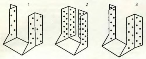
It is already designed for a specific beam section and is represented by several standard sizes and two design options: 1 and 3 - for subsequent finishing in order to hide their vertical “wings” curved outward for fasteners; 2 - without subsequent finishing ("wings" are hidden).
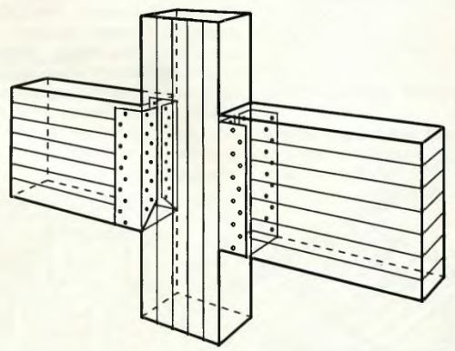
The beam support is used in the construction of wooden floors, when it cannot be supported on the walls or columns themselves (for example, a floor installation in an existing building). Each connection is fixed on both sides with bolts and nails. In our example, two short beams are connected by poles through a B-pillar, a practical solution to a common problem.
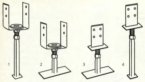
Shoes for bearing racks and columns are installed (anchored) in concrete foundation during its pouring (and bolted to the finished one). There are various designs of shoes: 1 and 4 - for pouring into concrete; 2 and 3 - bolted; 1 and 2 - the rack is installed in the shoe; 3 and 4 - the shoe is cut into the rack; all structures, being mounted, can be rotated around their own axis and adjusted in height.
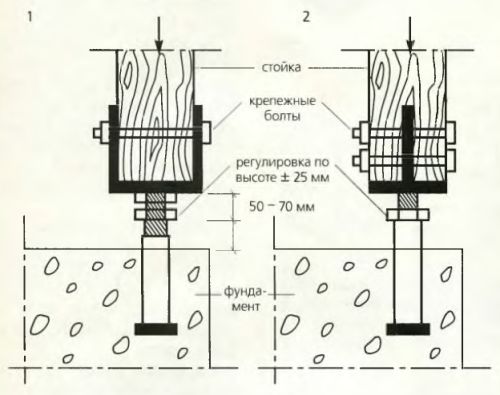
The rack or column is installed on the mounted shoe and fixed with the required number of bolts: 1 - the rack is installed in the shoe; 2 - the shoe is cut into the rack. In this state, the rack can be turned to the desired angle around the axis and adjusted in height in the range of ± 25 mm.
Connectors
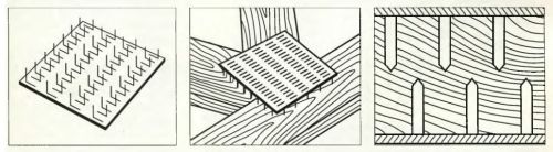
Connectors: designed for complex nodal connections in roof trusses covering spans of 7.5 meters or more. The connector is a flat plate, in the body of which, by stamping, needle nails (or spikes) of a certain configuration are cut out. They are made both in the form of plates with specific dimensions, and a tape (width 25 - 152 mm), cut to the required length. The connectors are pressed into the wood with spikes (across the fibers) on both sides of the joint. The principle of working with connectors is well understood by the example of mounting a roof truss, where two connectors (on 2 sides) allow you to assemble a unit from 3 parts at once.
Connectors - special connecting fasteners
Connectors - special connecting fasteners. It allows you to assemble and strengthen complex nodal connections of 3 or more parts, for example, in roof trusses with spans of more than 7.5 m. The connector is a flat plate, in the body of which needle spikes are cut. They are made in the form of finished plates with specific dimensions or tape (width 25 - 152 mm). They are pressed into the wood with spikes on both sides of the connection.
You can often hear the opinion that frame houses are one of the simplest, most rational and inexpensive types of building structures. Based on this idea, many developers choose frame technologies for construction, thinking about savings and even about the possibility of building a house on their own. Unfortunately, the idea of simplicity and low cost of frame technologies applies only to those that do not correspond to any building codes and rules for buildings that are built by guest workers and inexperienced do-it-yourselfers. However, the same can be said about the construction of log houses made of wood with your own hands.
Frame technologies really have many advantages, but only in those cases when the house is being built by experienced builders from industrially produced components for frame housing construction. An inexperienced or illiterate builder, working with frame technology, can make many more mistakes than when building a house from solid wood or stone materials. Where, when building a house from massive wall materials, only a few technological operations are required, frame technologies will require a much larger number of technological “passages”. With more operations, the risk of errors, non-compliance with technologies and improper use of materials increases significantly. Therefore, frame houses built without a project and attracting qualified specialists “at random” or on trust in guest workers can be short-lived, they will soon require overhaul due to unsatisfactory consumer qualities (freezing, wetting of the insulation, high heating costs, rotting of structural elements, destruction of both individual elements and the entire structure as a whole). Unfortunately, in Russia the list of regulatory construction documentation for the design and construction of frame houses is significantly limited. At present, the set of rules of 2002 SP 31-105-2002 “Design and construction of energy-efficient single-family residential buildings with wooden frame, based on the outdated 1998 National Housing Code of Canada.
In this article, we will provide short review the main mistakes and violations of the technology of frame housing construction.
Construction without a project.
This is a universal "general" mistake when choosing any construction technology. However, it is in frame technology that the price of errors can be especially high and lead to cost overruns instead of saving them both due to the use of an excess amount of material (a frame made of large cross-section timber) and the need for repairs due to insufficient sections of beams, a rare step of their installation. destruction of structural elements due to unaccounted for loads, incorrectly chosen methods of connection in nodes and fastening materials, biological destruction of wood due to a violation of steam and moisture removal.
Construction from a tree of "natural humidity".
Practically nowhere in civilized countries do they build houses from raw wood, just as before in Russia they never built houses from freshly cut tree trunks. SP 31-105-2002 clause 4.3.1 states: « Bearing structures(frame elements) of the houses of this system are made from sawn softwood, dried and protected from moisture during storage. Raw wood is only a semi-finished product for the production of building materials. In Russia, sellers and suppliers delicately refer to raw lumber as “natural moisture” wood. Recall that a freshly cut tree has a moisture content of 50-100%. If the tree was rafted on water, then the humidity is 100% or more (the amount of water exceeds the amount of dry matter). "Natural moisture" usually means that the wood has dried out a little during processing and transportation, and contains between 30 and 80% moisture. When drying in the open air, the amount of moisture decreases to 15-20%. The normal equilibrium moisture content of industrially dried wood in contact with the atmosphere will be 11-12%. When drying a wet tree, the length of sawn timber is reduced by 3-7%, and the volume of wood by 11-17%. The use of wood of "natural moisture" for the construction of frame houses leads to uncontrolled shrinkage of the tree, which changes the linear dimensions of the structural elements, can lead to deformations, cracking and rupture of wood with the destruction of fasteners. When the wooden frame shrinks, numerous cracks and gaps open, significantly increasing the thermal conductivity of the walls of the frame house, tearing insulating materials that prevent the penetration of moisture. When wood shrinks, its density increases, which leads to better vibration and sound transmission.
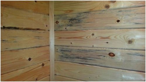
Construction from lumber without preliminary antiseptic treatment.
Even in the most properly designed frame house, a certain amount of condensate is inevitable on the sections of the media, which are much more in frame houses than in buildings made of massive materials. A moistened tree containing polysaccharides in its structure is an excellent nutrient medium for various forms of microflora and microfauna, whose representatives are able to destroy the structure of a tree in a short period of time. SP 31-105-2002 (clause 4.3.2) states that all wooden elements located closer than 25 cm from ground level and all wooden elements not made of dry wood are subject to antiseptic treatment.
Incorrect use of materials.
In classical frame technology corner posts frames should not be made from a bar or from three boards knocked down closely - in this case, increased heat loss through "cold corners" is provided. The correct "warm corner" is assembled from three vertical posts located in mutually perpendicular planes.
For sheathing the frame, materials capable of bearing loads are used. For example, OSB should be structural and designed specifically for outdoor work.
Insulation of vertical frame walls is permissible only with rigid insulation boards. Backfill and roll insulation due to shrinkage and slipping over time can only be used on horizontal surfaces or in roofs with a slope of up to 1:5. When using economical versions of low density insulation boards, it is recommended to fix each row of boards with spacers between the boards to prevent slipping. This decision increases the cost of the structure, increases the thermal conductivity of the wall, so it is more profitable to use a high-quality, more expensive, higher-density insulation. The size of the openings between the racks of the frame should not exceed the transverse dimension of the insulation boards - 60 cm. It is even better if the size of the opening is reduced to 59 cm in order to exclude gaps between the racks and the insulation boards. You can not fill the walls with scraps of insulation - there will be many gaps.Incorrect fastening of materials.
Black self-tapping screws can only be used for fastening sheet materials. The use of black self-tapping screws in a power frame, especially in a frame made of damp wood, can lead to rupture of these unreliable fasteners with low shear strength.
In all cases of assembling the power elements of the frame, galvanized nails, or chrome-plated or brass-plated self-tapping screws with a minimum diameter of 5 mm, are used. The use of perforated steel fasteners without ligation of wooden elements does not always guarantee the design strength of the frame.
Fasteners of beams and other elements of the load-bearing frame must not be fastened to OSB boards, especially with nails.
When nailing sheet elements or screwing them with self-tapping screws, it is unacceptable to sink the cap or head deeper than the plane of the surface of the material. From the point of view of structural strength, the penetration of the head or cap by half the thickness of the material is considered a missing fastener and must be duplicated by a correctly installed self-tapping screw or nail.
The minimum distance from the edge of the sheathing material to the head or head of the fastener is 10 mm.
Since 2012, the International building code for residential buildings (International building code, paragraph 2308.12.8) requires to prevent shear during an earthquake, wind load, etc. fix the frame of all newly erected frame buildings to the foundation anchor bolts through clamping plates with a size of at least 7.6 by 7.6 mm with a steel thickness of the plates of at least 5.8 mm. The minimum diameter of bolts or anchors is 12 mm.
Construction of frame houses using "innovative" technologies.
The most widespread technology in the world frame construction provides for the sequential assembly of "platforms" - ceilings with floors, followed by the assembly of walls on them and their installation in a vertical position. In this case, it is convenient for builders to move along a solid surface, it is convenient to work with materials, any deviations from the design position can be eliminated before the construction of walls begins, and the ceilings themselves rest securely on the underlying structures. For some reason, domestic builders are trying to invent their own options for building a frame house with assembling walls "in place", mixing the technology of building a frame house with half-timbered technology or "pillars and beams" with the device of floors last, which is fraught with the need for insertion or "suspension" floor beams, the need to move on temporary decking, with a high probability of injury when falling from a height.
Errors in working with floor beams of a frame house.
Most mistakes are made with the fastening of beams. It is best to rest the beams on the upper trim of the load-bearing walls, on the girders. It is forbidden to reduce the cross section of the beam by washing down the cutout for joining with the strapping. If necessary, joining the floor beam with strapping beam or by running the beam must be fastened through the underlay support bar with piercing with nails, or with the help of steel beam supports. The steel support of the beam must have a height equal to the height of the beam and be fastened with nails through all mounting holes. Fastening beams with undersized supports, not punching all mounting holes, fastening with black screws, fastening only on nails without a support bar are errors.
The most common pitch of floor beams in the world practice of frame housing construction is from 30 to 40 cm. Such a step of the beams makes it possible to obtain strong floors that do not bend under shock loading. Overlapping with a step of more than 60 cm is generally not recommended. The minimum thickness of sheet materials for flooring on floor beams is 16 mm for a beam spacing of 40 cm.
Often, bending beams are rallied flat from the boards, and not installed on the edge.
Load bearing capacity flooring increases if the covering sheet material of the subfloors is additionally glued to the floor beams.
The bearing capacity of frame floors can be increased by rigid cross-beam bracing. Such connections are installed in increments of 120 cm and can serve as a support for internal non-load-bearing partitions (through the subfloor). Also, the cross struts serve as an obstacle to the spread of flame in case of fire.
How to drill holes in floor beams correctly:
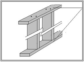
I-beams:
Composite H-beams can only be cut or drilled in specific locations per manufacturer's specifications. The upper and lower elements of the I-beams should not be violated. No more than 3 holes are allowed per beam. One hole up to 40 mm in diameter can be drilled in any part of the I-beam, with the exception of the bearing parts. Glued I-beams Wood-OSB-Wood have the designation "Top". When self-manufacturing beams based on OSB, the direction of the force axis of the material should be taken into account.
Sawn timber floor beams:
Mistakes in working with frame house cladding.
According to foreign building codes and the recommendations of the American Engineering Wood Association (APA), sheathing the frame with OSB boards can be done both vertically and horizontally. However, if the OSB board is sewn along the frame studs, then the force axis (indicated on the OSB panel by arrows and Strength axis) will be parallel to the studs. Such an arrangement of plates is useful only to strengthen the weak racks of the frame, working in compression without significant lateral and tangential loads (which is almost unrealistic in real operating conditions). If the OSB boards are sewn perpendicular to the uprights, they reinforce the frame of the building to absorb the tangential and lateral loads that occur when exposed to wind, and the movement of the base during the movement of soils. Particularly relevant is the horizontal sheathing with OSB panels in frames with no slopes, to give the required structural rigidity. If the OSB sheets are laid across the uprights, then the force axis will be perpendicular to them, and the OSB sheets will withstand a large compressive and tensile load. So, for example, in the domestic joint venture 31-105-2002. "Design and construction of energy-efficient timber-framed single-family residential buildings" provides (table 10-4) the recommended minimum plywood thickness parameters for framing cladding: if the plywood fibers are parallel to the frame studs at a 60 cm step, then the minimum plywood thickness is 11 mm. If the plywood fibers are perpendicular to the posts, then thinner sheets with a thickness of 8 mm can be used. Therefore, it is preferable to sew OSB sheets with the long side not along, but across the racks or rafters. For exterior cladding of one-story frame houses, OSB 9 mm thick can be used. But during construction two-storey houses and any houses in areas with strong winds, the minimum thickness of OSB for exterior cladding is 12 mm. If a frame house sheathed with soft fiber boards of the Isoplat type, then the frame structure must have jibs to ensure lateral rigidity of the structure.
Between all sheet materials of the sheathing, gaps for thermal expansion of 2-3 mm should be left. If this is not done, then the sheets will “swell” during expansion.
Docking of sheathing sheets is carried out only on racks and crossbars. The sheets are sewn "in a row" in order to ensure greater strength of the load-bearing frame structure with chain ligation. The outer skin must connect the wall frame with the bottom and top trim.
« Pirogi, floors, walls and roofs of a frame house.
The main mistake in the design of frame pies of floors, walls and roofs is the possibility of wetting the insulation from moisture penetration. General rule building walls in heated rooms - the vapor permeability of materials should increase from the inside to the outside. Even in the floor, where the opposite is often done: the vapor barrier is laid on the side of the ground, and the vapor-permeable membrane is laid on the side of the room.
In any insulated cake of a frame house, there must be a continuous layer of vapor barrier from the inside. "Solid layer" really means that the vapor barrier must not have any defects: the sheets must be glued with an overlap along the entire contour to be protected, without exception. For example, at the frame assembly stage, almost all builders forget to lay a vapor barrier under the junction of internal partitions to external walls in accordance with typical junction schemes of paragraph 7.2.12 of SP 31-105-2002.
Additionally, all gaps between the sheet materials of the skin during wet rooms and on the roof must be glued with waterproofing materials to prevent moisture from getting inside the insulated "pies".
In addition to preventing moisture from entering the insulated cake, moisture should also be removed: outside frame wall must be either sheathed with OSB boards, which are a “smart” vapor-permeable material capable of increasing vapor permeability when the environment is moistened, or protected by a semi-permeable membrane that ensures the removal of moisture from the insulation. Cheap single-layer membranes have unsatisfactory vapor permeability and require an air gap between the insulation and the membrane. Also, cheap single-layer membranes do not protect well from the penetration of moisture from the outside. It is preferable to use expensive superdiffusion membranes, which have really good vapor permeability and can be mounted directly on the insulation.
Frame house ventilation.
Figuratively speaking, the internal space of a properly built frame house is identical to the internal space of a thermos: heat loss through the walls is very small, and moisture transfer through the walls is most often practically absent (but can be maintained during use). Accordingly, it should be taken out. Without thought it becomes impossible. In a frame house, ventilation valves must be installed in each room, or windows must have a micro-ventilation mode or built-in slotted ventilation valves. Exhaust ventilation must be installed in the kitchen and bathroom. Abroad frame houses for permanent residence almost never build without supply and exhaust ventilation with a recovery system.
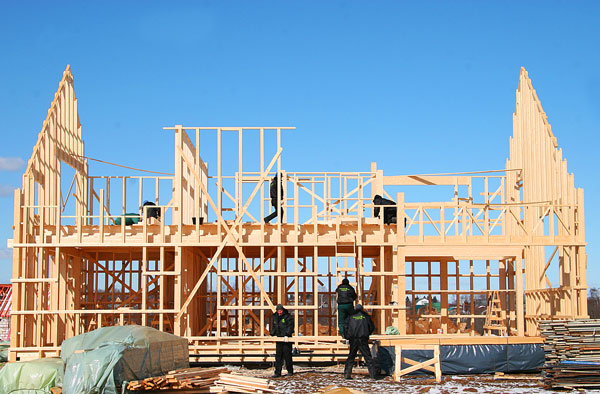
At the end of the article, we give illustrations of the widespread "folk" design of a frame house, in which, upon closer examination, there is not a single correctly executed element.
The typical mistakes that we have described in the article are easily preventable. Before you start building your first frame house or hire builders, study in detail, albeit slightly outdated, but the only set of rules available in Russian for frame housing construction SP 31-105-2002. Paying attention to all the details and subtleties of the creation of the power frame of the building and ensuring the durability of its operation, you can avoid costly mistakes when building or ordering your frame house.