Important! When creating a drawing of a house, it is necessary to proceed from the number of people who will live in it. It is advisable to also provide one or two guest rooms.
Independent house planning can be done in the following options:
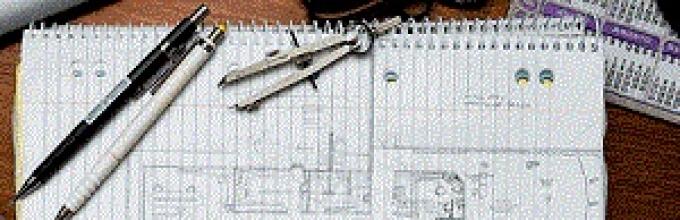
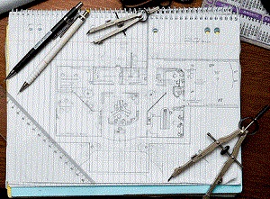
- The simplest option. The building plan is drawn on a sheet of paper by hand. In this case, you need graph paper. If it is not there, then you can use a sheet with a checkered line.
Advice! The above option is suitable for people with drawing skills. IN otherwise the layout will have flaws and inaccuracies.
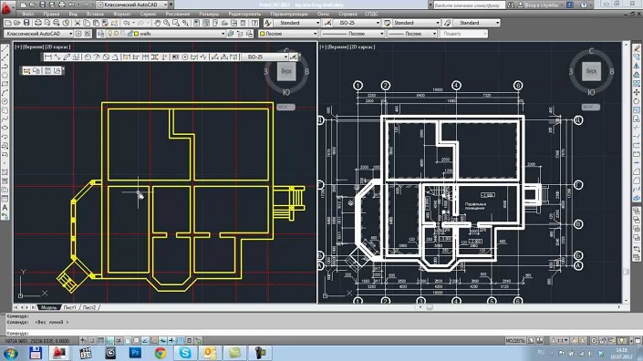
- The most accurate option. The most obvious option for creating a house layout is to use a computer design program. Such programs allow you not only to make basic sketches, but also to create a full-fledged drawing two-story house, meeting all building codes.
Advice! To avoid possible errors in calculations, it is advisable to use only licensed software.
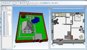
- The most creative option- this is the use of a 3D editor. Such a project turns out to be three-dimensional and perfectly conveys not only the size and location of the rooms, but also the design ideas of the author.
Video instructions about step-by-step independent planning residential building in one of the specialized programs
What does a complete house project look like?
A complete house design involves not only the appearance and layout, but also Full description all construction parameters, utilities and characteristics of building materials. In other words, this is complete guide to action for builders that can give knowledgeable person
complete information about the future construction.
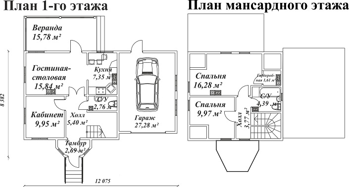
- Thus, complete house plans include: Architectural description of the building . This includes drawings of the house facade with dimensions interior spaces
- . The dimensions and location of windows and doors are indicated here, and all utility and residential premises are present. Calculation of design nuances , including truss structures
, house box, foundation and roof. All these elements must be depicted schematically in the drawings with calculations and detailed markings attached.
- Treatment of the façade with a water-repellent agent Electrical network diagram
- . Here, the connection of the house is described in as much detail as possible, the features of the electrical wiring with wiring diagrams, the location of sockets, etc.. This includes a floor plan with the laying of vital communications - ventilation, water supply, sewerage, heating, gas, etc.
Thus, house designs are not limited to just one drawing, as some people assume, unaware of all the nuances of this process. Therefore, if you refuse the services of a professional designer, you should understand that before building a house you need a complete drawing up project documentation.
How a house plan is created
The layout of the building is based on handwritten or electronic drawings, for the correct implementation of which it is necessary to follow the following sequence of actions:
- The required scale is set on graph paper.
- The axes of the house are drawn.
- Next you need to draw the walls.
- We draw the internal partitions.
- Now you need to place windows and doors on the drawing.
- For each room, the name and area are indicated.
Advice! The development of a utility plan, electrical network layout, etc. should be carried out by a specialist. Therefore, if you lack knowledge in these industries, it is necessary to consult with an experienced designer who will help you avoid serious mistakes. The most unpleasant situation is when the project has been approved for construction, the house is built, and only then technical defects begin to appear, which are very difficult to eliminate.
Using a home design program
Today there are many computer programs, intended for the design of buildings. Among them there are both amateur ones, which cannot be considered as a serious instrument, and professional programs, used by specialists around the world. These include: AutoCad, Compass 3D and others.
A set of drawings developed in such a program has a number of advantages:
- Faster plan creation process.
- The program minimizes possible inaccuracies in calculations.
- Possibility of creating three-dimensional model Houses.
- Virtual planning of not only premises, but also utility networks.
- Quick learning even for those users who are not familiar with the basics of drawing.
- Wide functionality and a large set of tools for implementing any technical and design solutions.
- Lots of lessons and useful tips on the operation of programs on the Internet.
- The presence of built-in libraries that contain furniture, architectural elements and even Decoration Materials, which allows you not only to create a drawing, but also to imagine the appearance of the future home. This is very important in order to consider the project from the point of view of convenience, coziness, etc.
When creating a house drawing, you should consider the following recommendations from experts:
- The number of rooms, taking into account their functional purpose and location relative to each other. Here it is necessary to provide not only the main rooms reserved for each family member and functional rooms(bathroom, toilet, kitchen), but also a room where the whole family will gather (hall, living room), hallway, veranda, pantry, etc.
- The hobbies of each family member should also be taken into account when planning the house. For example, some houses have their own swimming pool, Gym, separate library, sauna, workshop, etc.
- It is better to make personal rooms small and cozy, but the hall where the whole family gathers, on the contrary, should be spacious.
- The nursery should be located next to the parent's bedroom.
How to make a good design project? Preparing a 3D model and the secrets of competent design. Video from Alexey Zemskov
Advice! If there are small children or elderly people in the family, this should also be taken into account when planning the house. Perhaps in this case it would be better to abandon the second floor or install the safest stairs with comfortable railings and deep steps. Goose-step structures are not permitted.
- For compact placement of the water supply and sewer system, it is advisable to place the kitchen, boiler and utility unit in one line.
- To effectively retain heat in winter time It is desirable to have an insulated veranda or vestibule in the house.
- When calculating the area of a building, it is necessary to take into account that there must be at least 8 m2 of living space per adult.
Advice! Young families should consider the likelihood of adding to their family at the stage of designing a house.
- It is desirable that the location of the windows be south or east.
Conclusion
Many people are interested in how to make a plan or drawing on their own, but not everyone understands how important the design stage is. Above we discussed the main nuances of creating complete project Houses. Here it should be understood that designing a house requires an integrated approach and attention to a number of features.
The main function performed drawings of building facades- this is to give an idea to those who study them and work with them about what kind of appearance the building has, what its architectural features are, and in what relationship its individual elements are located. The following varieties are distinguished facades:
- Main
- Dvorovy
- Lateral (end)
Main facade V modern construction and architecture refers to the view of a building that opens onto it from the side of a square or street. As for other types of facades, their names come from their location in the building itself. As a rule, in architectural projects facades located on all sides of buildings are indicated. In cases where the facades have a complex configuration and are located not in one, but in several planes, then their parts, according to current norms and rules, can be depicted in several separate drawings. If several (two or more) facades of a building are absolutely identical, then only one drawing is made for them.
Facade drawings buildings should contain images of such elements as:
- General appearance of the structure
- Window location
- Door location
- Location of balconies and loggias
- Location of platbands
Facade drawings panel and large-block buildings also include cutting walls into panels and blocks.
Working drawings of building facades are usually made in such a way that only the extreme coordination axes are depicted on them without putting dimensions between them. On the right and left sides of the drawings of building facades, elevation marks of the ground level, top and bottom of openings, plinth, top of the roof and cornice are placed. Exactly how this or that facade is named is determined by the extreme coordination axes, between which the section of the building shown in the drawing is located. In addition, it is allowed to indicate the name of the building’s facade with an axis mark located on the facade wall (for example, “Facade 1 – 7”, “Facade A - B”, “Installation diagram of the facade 1 - 14”, etc.).
Residential building facade
When constructing drawings of facades, you should choose a scale that would be minimal, but at the same time sufficient to show the openings, relief Facade of an industrial building
Drawing the facadeWhen drawing building facades, all constructions must be carried out in the following sequence:
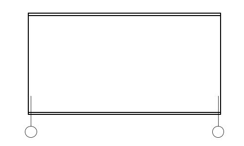
External contour of the building
Drawing of coordination axes, designation of the general outline of the structure, as well as (if any) its protruding parts.
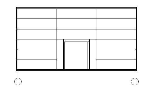
Architectural elements facade
Application of door and window openings, slabs of canopies over entrances, balconies, cornices, as well as other existing façade elements.
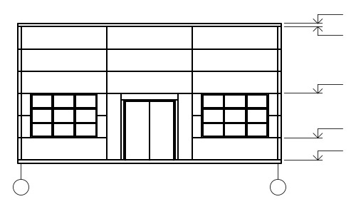
Development of the facade of the house
Applying doors, window frames, balcony railings located on the roof of chimneys and ventilation pipes, placing elevation signs.
Development of building facades
Next, they check whether the facade corresponds to the sections and the plan, and carry out its final outline. If the buildings are large-block or panel, then seams are drawn between the blocks and panels.
To depict visible contours in facade drawings, a solid thin line is used. To draw the ground contour line, you can use a thick line extending beyond the boundaries of the facade.
According to current standards and regulations, how is a building façade drawing made? What are the correct names for the different projections of a building?
Let's get to know general rules execution of construction drawings.
The photo shows a sketch of the facade from those times when the requirements for design documentation were different from today.
General provisions
We will begin the answer to the question of how to draw the facade of a building by listing the requirements common to all construction drawings and diagrams.
Terminology
- All construction drawings are obtained by projecting a certain type of building onto a plane.
- The actual drawing of the facade of a house is its frontal projection onto a plane parallel to the facade.
- The projection of a section of a building in a longitudinal or transverse plane is, respectively, a longitudinal or transverse section.
- If a horizontal section of a building is transferred to paper, it is usually called a plan. Depending on the level at which the cut is made, this could be a plan for the basement, first floor, and so on.
- A top view of a site that includes a building or a group of buildings and structures is usually called a master plan.
- Finally, no matter what object is depicted - the basement kindergarten, the facade of an industrial building, the facade of a cottage, or a toilet on summer cottage- all these images have a common name: architectural and construction drawings.
Despite the proliferation of electronic media, drawings must be printed on paper.
Regulations
Sections, plans and drawings of building facades must be made in common system ESKD (unified system of design documentation). Its standards are determined by GOST 2.301-68 - GOST 2.307-68.
What exactly is regulated?
- Sheet formats for all drawings.
Important: format requirements imply certain aspect ratios of the sheet itself, and not the drawing frame.
- Large-scale series of images.
- Thickness of lines.
- Name of image elements.
- Drawing fonts.
- Methods of depicting various objects in drawings.
- Graphic symbols of various materials.
Scales when compiling master plans The following objects can be used:
- 1:200;
- 1:5000;
- 1:10000;
- 1:20000;
- 1:25000;
- 1:50000.
In drawings of facades and plans, of course, larger scales are also used.
A 1:1 scale can be used when transferring cornices onto paper complex shape and other small elements. However, this is rather an exception. Magnification scales are not used in architectural and construction drawing.
Rules for the execution of drawings
In order to correctly create drawings of house facades, floor plans and other architectural and construction schemes with your own hands, you need to adhere to fairly strict rules.
- The thickness of the main line should be the same for all parts of the drawing, made to the same scale. An exception is section drawings: visible contour lines may be drawn thin line.
- Names, headings and symbols in the drawing field can be written without slanting. But dimensions and other inscriptions on the arrows are written oblique, with an angle relative to the base of the line of about 75 degrees.
- The total number of dimensions in the drawing should be, as common sense suggests, sufficient to carry out construction work. In this case, duplication of the same size on different elements of the image is allowed.
- Dimensions are given in millimeters without units of measurement. However, the level above the ground is indicated in meters accurate to the third decimal place.
Traditionally, all dimensions in drawings are indicated in millimeters. The rule is not absolute; but other units of measurement should be specified in the notes.
Attention: it is also permissible to indicate dimensions in centimeters, provided that the units of measurement are specified in the notes to the drawing. And in this case, the units of measurement are not indicated separately.
Features of facade drawings
We have listed the general provisions. Are there any nuances related specifically to the facades that primarily interest us? How to draw the façade of a building in accordance with current regulations?
Here are the instructions.
- The facade drawing should give a clear idea of appearance facade of the building (see), about the proportions and size of individual elements.
- If the facade and plan are on the same drawing, they are carried out on the same scale and must be in projection connection. What does this mean? Only that the plan is located on the drawing under the facade.
- The facades of different sides of the building have their own names, which are indicated on the drawing. There are main, courtyard and side (end) facades.
- The drawing indicates all the structural details that will be present in the real building. For example, the main facade of the school in the drawing should be equipped with a porch, the courtyard - fire escape; cornices, dormer windows and other seemingly small details are drawn.
- In a technical project, it is customary to show its own shadows and the shadows falling on it on the façade. To do this, the drawing is painted with watercolors or shaded with dry grated ink.
- The façade drawing does not indicate horizontal dimensions. However, on one side, at a distance of 15-20 millimeters from the contour of the facade, general height dimensions and level marks are set for the ground, windows and doors, plinth, cornice and roof ridge and the top points of pipes and ventilation.
- Axes are applied at the bottom of the façade expansion joints and changes in building height.
Before us is a drawing of the facade made according to all the rules. Quite complex, I must say. It was taken from a very real building - the Bolshoi Drama Theater on the Fontanka embankment in St. Petersburg.
Conclusion
You can find more information about constructing drawings in the video at the end of the article. In addition, it is useful to know that the price including full set drawings, starts from 10,000 rubles for standard solutions. Exclusive projects can cost tens of times more. Good luck in construction!
Facades- orthogonal projections of the building onto a vertical plane - the outer side of the building. The facade drawing gives an idea of the appearance of the building, its architecture and the relationships of its individual elements. There are main facades, courtyard facades and side or end facades.
The main facade is the view of the building from the side of the street or square. The definition of other facades follows from their name. The project usually gives facades of all sides of the building. With its complex configuration (L- and W-shaped, etc.), facades located in different planes can be depicted on separate drawings. One drawing is made for identical facades.
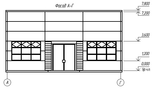
The name of the facade is determined by the extreme coordination axes, between which the building section shown in the drawing is located, or by the mark of the axis located in the facade wall, for example, “Facade 1-7”, “ Facade A-B", "Installation diagram of the facade 1-13", etc. The name of the facade is inscribed above the image with a minimal gap (Fig. 10.12. D).
The scale of the facade should be minimal, but sufficient to show the relief of the wall, openings, holes in the walls, etc.
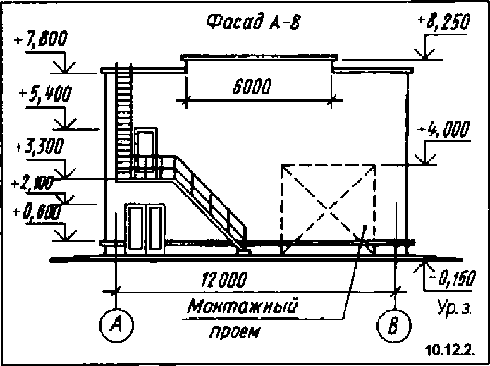
On the drawings of the facades, it is advisable to indicate expansion joints, fire escapes, external drainage pipes, ramps at the gates, louvered grilles, including those installed instead of window sashes, etc. Hatching marks out sections of walls made from a material different from the material of the entire building. The dashed lines show the installation openings to be laid (Fig. 10.12.2).
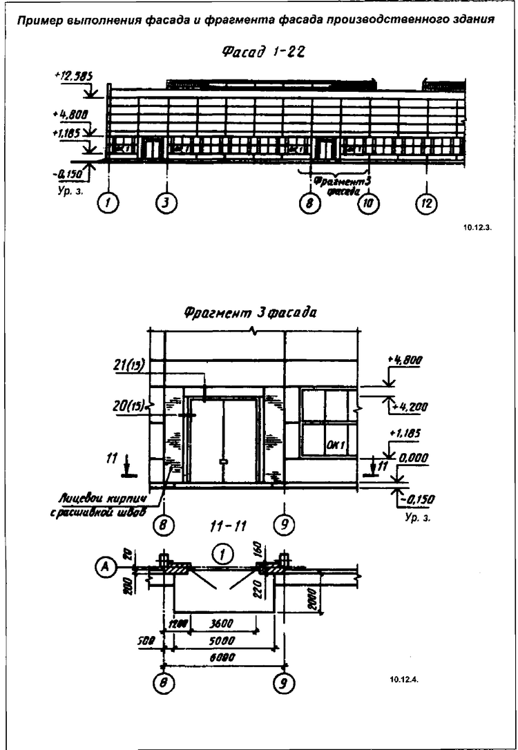
In industrial buildings with a long facade with a rhythmic arrangement of windows, it is allowed to show the pattern of window sashes only in the outer two or three openings at both ends of the building; on longitudinal types of lanterns - also only at the ends, in civil buildings - in all window openings. However, the degree of detail when drawing facades of civil and industrial buildings depends on the scale. The design of window frames, the type of doors and gates are shown only on facades made on a scale of 1:100 and larger; at smaller scales, only the contours of the sashes and openings are drawn.
If there are complex areas on the facade, they are depicted separately in more on a large scale, i.e. a fragment of the facade is being completed.
The main drawing of the facade must contain a link to its fragments indicating the number of the sheet on which they are placed. Most often this is a curly bracket, under which the sheet number is indicated (Fig. 10.12.3). In Fig. 10.12.3 shows the facade of an industrial building, on which the fragment shown in Fig. is highlighted. 10.12.4. Above the fragment there is an inscription like: “Fragment of the façade.”
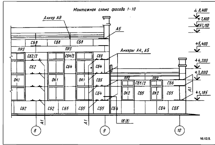
In buildings made of prefabricated structures (large blocks, panels, etc.), fragments of the facade are not drawn out, but are replaced with references to the layout of walls or facades (Fig. 10.12.5). On fragments of the facade, all the details are shown in detail and the necessary marks and inscriptions are applied.
The dimensions available on the plan and section make it possible to draw the facade of the building.
The completed drawing is prepared with the following data. In buildings of all types, coordination axes are shown located along the edges of the facade, at expansion joints, in places of ledges in the plan and differences in building heights. In industrial buildings, coordination axes are also shown at one of the sides of each gate opening.
As a rule, dimensions are not indicated on facade drawings, with the exception of the dimensions for linking elements that are not identified on plans, sections and fragments (Fig. 10.12.2 and 10.12.6).
The facade drawings indicate marks of the ground level, the top of the walls, entrance areas and facade elements located at different levels. On the drawings of the facades of industrial buildings, marks are also placed on the top of the walls, the bottom and top of the openings. It is advisable to rotate the mark shelf away from the image.
On facades, reference circles mark the details available in the project, if they are not shown on the details of plans and sections. If there are fragments of facades, marking should be carried out only on fragments. On the facades, window blocks are marked as OK-1, OK-2, etc. or diagrams for filling window openings, if they are not shown on the plans.
The mark for the type of filling of the opening is placed on the facade inside the contour of the window opening, and for small openings - under it or on the extension line. If all window openings of a building have the same type of filling, it is not marked on the facade.
On the facade drawing, marks and dimensions are applied, as well as reference to openings and openings not indicated on the plans and sections. In addition, indicate the type of finishing of wall sections that differ from the rest (predominant); external fire and escape stairs, adjacent galleries. In large-block and panel buildings, the walls are cut into blocks and panels.
The facade drawing, which is one of the projections of the building, is constructed on the basis of plan and section drawings. All preliminary constructions are carried out using thin lines.
The drawing of the facade of the building is drawn in the following sequence:
- First, draw a horizontal straight line with the thickness adopted for the outline of the facade. It extends beyond the contour by approximately 30 mm. This line serves as the foundation on which the facade of the building is built (Fig. 10.12.7).
- Then draw a second horizontal line at a distance of one and a half millimeters from the first - the blind area line.
- Thin lines draw the horizontal contours of the base, bottom and top of openings (windows and doors), cornice, ridge and other elements of the building,
- Next, draw vertical lines of coordination axes, walls, windows and doorways and so on.
- They draw out balcony railings, chimneys and ventilation pipes and other architectural details of the facade,
- Reference circles are applied, indicating the façade elements depicted on the fragments, circles of coordination axes, extension lines and elevation signs, and, if necessary, dimension lines.
- Place elevation marks, axle marks, dimensions, if necessary, and complete all required inscriptions. To depict the facade, a different construction order can be used.