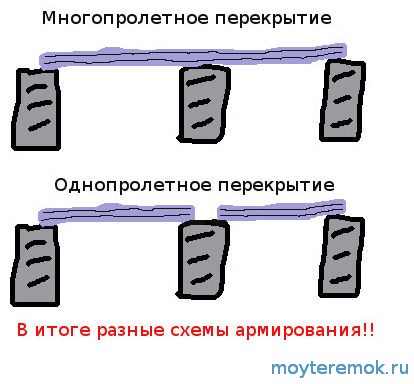
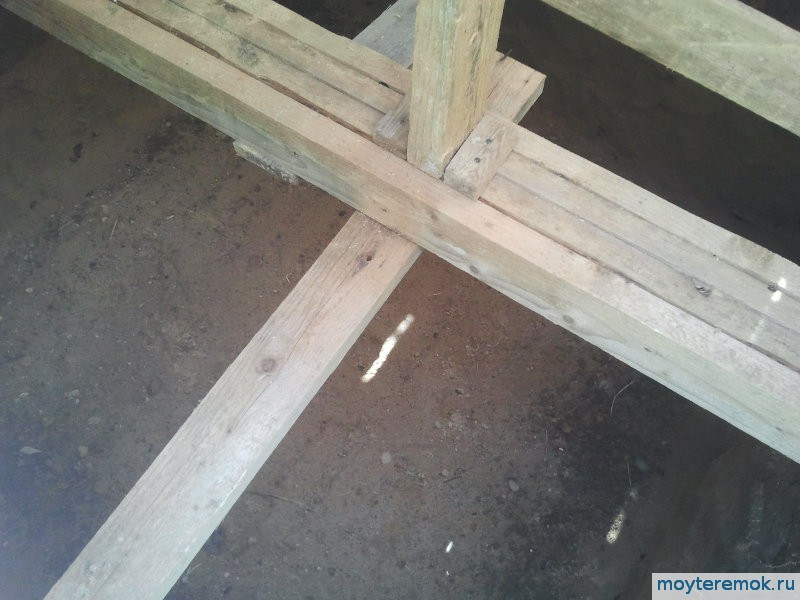
In the case when there will be more than one floor in the house under construction, the issue of laying floors cannot be avoided. Functionally, they are tasked with separating floors and carrying a payload in the form of their own weight, people and furniture located on them. Therefore, their strength and load bearing capacity should be sufficient, but at the same time it is highly desirable to reduce their total weight, since excessive loads are undesirable either for walls or for the foundation. To lighten the weight while maintaining the strength characteristics, a variety of designs are used, including the so-called ribbed ceilings.
Structural features of a ribbed monolithic ceiling
Let's see what this type of construction is and what are the prospects for its use in private construction.
Ribbed monolithic floors consist of beams that can go in one or two directions, and a slab connected to the beams into a single structure (that is, the beams work together with the slab resting on them). Such structures are used in the construction of buildings with large spans ( industrial buildings, shopping centers, subway, water protection, utility facilities, etc.).
 bidirectional ribbed floor
  ribbed slab formwork
The use instead of a flat reinforced concrete slab is due to a decrease in the consumption of concrete during the construction of the ceiling and, as a result, a decrease in the load on the load-bearing walls and foundation. Reducing the load on bearing structures buildings allows architects to create more interesting structures in their design. Not a secondary factor is the reduction in the cost of pouring concrete and reinforcement. To create ribbed floors, concrete of class B15-B25 and reinforcement of the following classes are used: A240, A300, A400, B500. The choice of class depends on the implementation of a specific design task. The manufacture of this type of interfloor slabs is no different from others. reinforced concrete structures, with the exception of the principle of using a special removable formwork. circuit diagram And appearance designs you can see in the picture. It is due to the shape of the formwork that the “ribs” are eventually created.
Interfloor ceilings on - environmental friendliness combined with economy.
WITH general terms we figured it out. Now let's talk about the applicability of ribbed monolithic ceilings in the construction of cottages and country houses For permanent residence. There are enough on the web a large number of information about creating such structures with your own hands. Such attention to the presence of "ribs" in the interfloor reinforced concrete floor is determined, first of all, by the desire to save on its construction. However, it is worth take into account the following points:
- A competent design calculation is required;
- Construction companies they offer for rent removable formwork and racks necessary for the manufacture of ribbed slabs, however, renting such formwork will cost much more than for a classic monolithic flat slab, which may ultimately offset the savings on concrete;
- Creating formwork with your own hands (for example, from boards or OSB boards) is a rather lengthy and laborious process, i.e. you will have to take into account the high labor intensity of the work;
- In addition, the appearance of the ceiling with beams will not fit into every interior. It may have to be subsequently sewn up with drywall or other materials.
 bidirectional ribbed monolithic overlap
  roofing on corrugated board
Properly laid floors will make the structure reliable.
Do-it-yourself construction stages
The final construction of a ribbed monolithic slab should be a slab that is completely flat on top and has a beam reinforcing structure at the bottom. Moreover, the slab and beams are poured simultaneously, forming a single-monolithic structure, due to which it gains the maximum possible strength. Most often when self erection as formwork, special boxes made of impact-resistant plastic are used. Formwork can also be made from foam sheets fastened together. They are laid on a specially constructed flooring, which is supported from below by racks - this will prevent the flooring from sagging from the moment the concrete mixture is poured until it is completely set. In order to save money, you can put wood on the flooring and racks, which will later be used for the construction of the roof. A more expensive option would be inventory formwork.
The openings that form the beams are laid along the entire length with a reinforcing cage, consisting of reinforcement bars with a diameter of 12-16mm (depending on the expected loads) and strapping (approximately 6-8mm). The entire upper flat part is reinforced with a reinforcing mesh (in 2 layers) in increments of 10-20 cm. The reinforcement is laid so that it is covered on all sides by a protective layer of concrete at least 20 mm thick. After all the components of the future floor are laid and securely fixed with racks, concrete pouring begins.

The overlap is considered ideal, the plane of which was flooded at a time, therefore self-mixing of the mortar in a concrete mixer is highly undesirable. This will lead to the fact that the plate will not have the same strength over the entire area and, consequently, there will be emergency places. In order to get a reliable overlap with a maximum margin of safety, use purchased concrete delivered to the construction site in a “mixer” (it is quite difficult to keep the correct dosage of all the components of the concrete mix on your own). Thus, you can pour the stove at one time, and it will turn out to be absolutely reliable.
Overlappings on a professional flooring
The type of ribbed monolithic ceilings also includes slabs poured over corrugated board used as fixed formwork. Decking also works as external reinforcement (with proper adhesion to concrete). It is worth mentioning that in this type of slab, the presence of proper reinforcement is mandatory. Therefore, we recommend entrusting theoretical calculations and selection of material to specialists.
Conclusion
Ribbed ceiling allows you to get a solid structure that separates the floors, with proper design and implementation. Design features save money construction material and lighten the load on the walls and foundation of the house, however, the process of erecting the formwork will be much more time-consuming and expensive than with other floor options, which should also be taken into account. This do-it-yourself overlapping option is more suitable for those who have a lot of free time and working hands. In other cases, in our opinion, it will be more efficient to purchase factory reinforced concrete slabs. And for small spans, a more rational solution would be to simply pour a flat slab.
FEDERAL AGENCY FOR EDUCATION
PERM STATE TECHNICAL UNIVERSITY
CONSTRUCTION FACULTY
DEPARTMENT OF BUILDING STRUCTURES
EXPLANATORY NOTE
CALCULATION OF A MONOLITHIC RIBBED COVER
Perm, 2009
Introduction
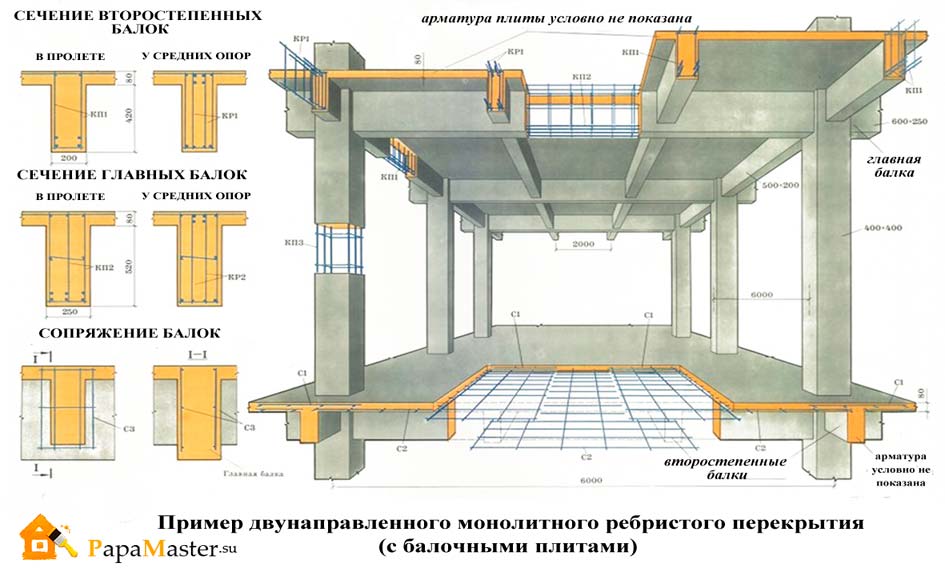
A monolithic ribbed floor consists of a monolithic slab, secondary and main beams, monolithically interconnected.
The essence of a monolithic-ribbed floor is that, in order to save concrete, it is removed from the tension zone and is concentrated mainly in the compressed zone. In the tension zone, the concrete is kept only to accommodate the working tension reinforcement.
The monolithic slab runs along the short side as a multi-span continuous beam, rests on the secondary beams and is monolithically connected to them.
Secondary beams perceive the load from the monolithic slab and transfer it to the main beams, monolithically connected to them.
The main beams are supported by columns and exterior walls.
1. Choosing an economical option
1.1 Monolithic floor with main beams along the building
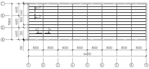
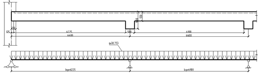
Secondary beam span l wb =6600 mm; main beam span l gb =8000 mm. We take the height of the plate h pl =80 mm For q vr =11,5 kN/m 2 and step of secondary beams 1600 mm (rice. 1).
Rice. 1. "Scheme in terms of monolithic-ribbed floor"
 .
.
accept the height of the secondary beam  .
.
 .
.
take the height of the main beam  .
.
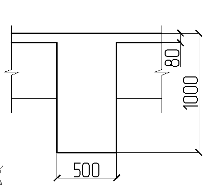
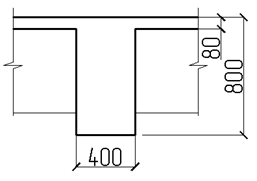
Rice. 2 “Section 1–1. Main beam»
Rice. 3 “Section 2–2. Secondary Beam"
Then the weight of all main beams:
The total weight of all concrete required on a monolithic ribbed plate, with the location of the main beams along the building:
3.2 Monolithic floor with main beams across the building
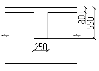
Secondary beam span l wb =8000 mm; main beam span l gb =6600 mm. We take the height of the plate h pl =80 mm For q vr =11,5 kN/m 2 and step of secondary beams 1650 mm (rice. 4).
Rice. 4 "Scheme in terms of monolithic-ribbed floor"
1. Determine the weight of concrete required per slab:
2. Determine the weight of concrete required for the secondary beam:
Determine the required height of the secondary beam:
accept the height of the secondary beam ![]() .
.
Determine the required width of the secondary beam:
accept the height of the secondary beam  .
.
Then the weight of all secondary beams:
2. Determine the weight of concrete required for the main beams:
Determine the required height of the main beam:
take the height of the main beam  .
.
Determine the required width of the main beam:
take the height of the main beam  .
.
Perhaps there is no other aspect of the construction of our house that I have not thought about as much as overlap. At first, when my knowledge of the materiel of this issue was not high, I leaned in favor of the option from one of the first TISEshnikov, very famous at that time Andre777. He still has a website on the Internet, where he already writes about the arrangement of his house and plot.
The essence of his technology was to fill concrete beams and a slab was already cast on them.
Since you can slowly pour one beam at a time, it seems that it’s easier this way. But having pretty much messed with the TISE foundation, I didn’t want to mess around like that and I became a supporter of other technologies, namely pouring everything and immediately to the maximum with ready-mixed concrete.
Also, Andryukhin's technology is much inferior to pouring everything at once (beams together with a slab), losing a large bearing capacity. The slab becomes a load on the beams. Because of this, beams have to be made larger in cross section and, in general, the output is still low bearing capacity and a large weight of the floor itself.
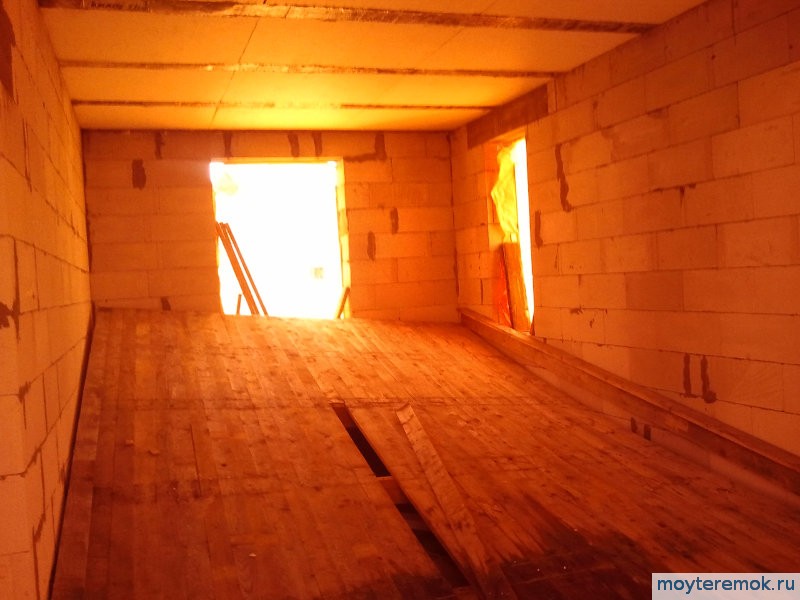
On the second floor, at first they wanted an overlap along wooden beams. Wooden floors it's not ice. Very poor soundproofing. If you then deal with this issue, it will be much more expensive than you thought.
Whether it's an option that came across to me much later and eventually included in my construction plan. They became a lightweight monolithic reinforced concrete ribbed floor from winder with ForumHouse.
This cover is designed for payload 550kg/m2 everywhere. This is the payload already minus the screed, partitions and its own weight.
Winder calculated the overlap for different spans. Choose a scheme for your span and go. You can also read kilometers of discussion of this overlap there. This will take more than one day, but you can download the guide (FAQ) from max68.2011 which will save you time.
Since both of our floors are ribbed monolithic from reinforced concrete, that is, they are similar, I will describe in one post:
- Overlapping over . Single-span, divided into two parts.
- Ceiling above the first floor. Multi-span.
We have spans in the grillage zone of 3.4m and 4.4m. There is a little more above the first floor, since the walls are already grillage 3.475 and 4.475. Therefore, we choose schemes for spans of 4m and 4.5m (the closest of those calculated by Winder). Scheme at the beginning of the article for a span of 4m (reinforcement F12). For a span of 4.5 m, the scheme is the same, only fittings F14.
Reinforcement in Windera schemes is designed for both cases (single-span or multi-span).
Our house has a bay window, these are additional difficulties in terms of overlapping. If, when laying the foundation, there are no problems here, because. the grillage goes around the entire perimeter of the bay area, but there is already a problem over the floors.
I turned to Winder with this question and he helped me a lot.
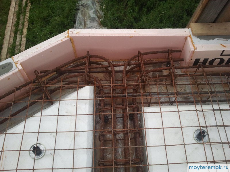
It was determined that the bay window requires a beam that will be built into the ceiling itself, as well as the rest of the ribs, and will be on the same level with it. The ribs of the monolithic ceiling will, as it were, rest on this bay window beam, which will become a continuation of the wall adjacent to the bay window.
Winder also calculated the bay beam itself. It turned out that if we want the beam to be flush with the entire ceiling, that is, 23 cm (21 + built-in warm floor), we need reinforcement with F18 rods four from below and four from above. Plus clamps (transverse reinforcement) from F8 reinforcement after 15 cm.
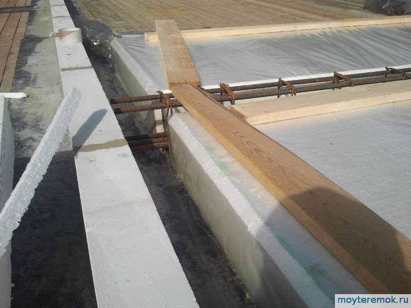
Such a beam should rest on at least 90 cm of the wall. Therefore, in order to avoid a cold bridge in this place, we use EPPS 5 + 2 cm. We look at the photo.
Fans of "breathable" materials, do not be afraid to use XPS on small areas. Even if you close a row of aerated concrete blocks with it, moisture will still evaporate from the closed blocks through the row above.
When using a built-in underfloor heating, the ceiling height is usually increased by the diameter of the underfloor heating pipe. The pipe is located between the grids of the upper part of the ceiling.
Took an Italian pipe Tiemme Cobra-Pex 16x2 mm. Before the crisis, not much more expensive than domestic Rosterm cost. Now more than twice as expensive 8). It cannot be compared with ours, it is much tougher and has more margin in terms of characteristics. On the ground floor, apparently, you will have to support a domestic manufacturer :).
We started the construction season as expected with the purchase of provisions. Then I decided to try the army rations of the Russian army. Very tasty too.

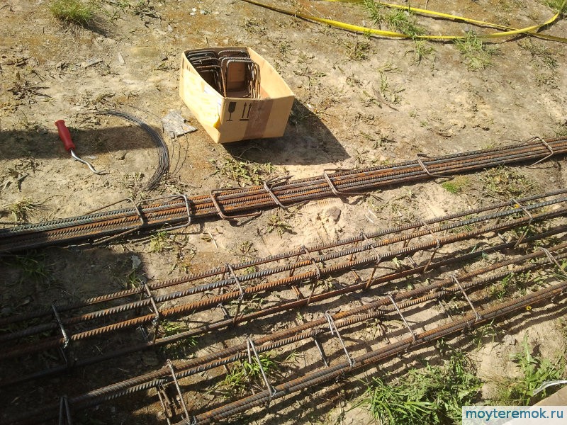
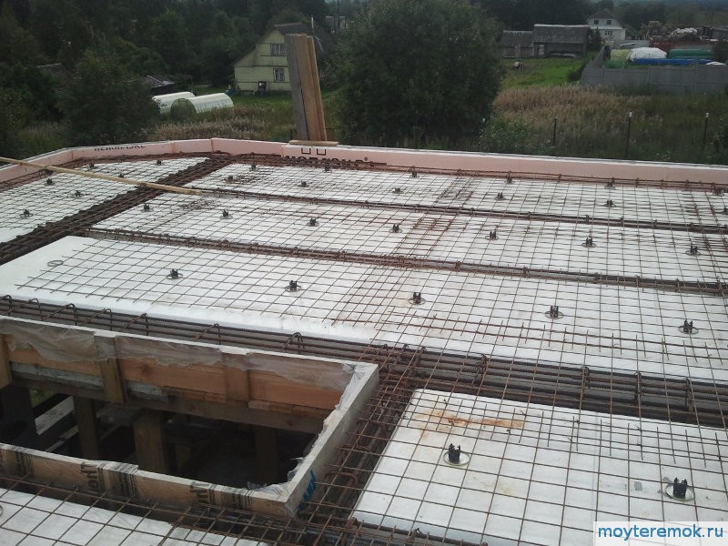
We knit reinforcing cages.
There is still a nuance how to do it. If done immediately on the entire area, then this is a multi-span ceiling (with an emphasis on the middle and outer walls), see fig. higher. If you do the overlap in parts. First, one half from the outer wall to the inner, then the other, then this is a single-span ceiling. Reinforcement of single-span and multi-span floors is different.
Here it is necessary to make a reservation. The fact is that if you use a multi-span scheme for one span, then everything will be fine except for the excessive consumption of reinforcement. The Windera scheme is such (universal with "fool protection").
Which single-span or multi-span floor to choose is decided depending on the initial length of your reinforcement in order to lay it as economically and efficiently as possible. fewer scraps. And it also depends on the technology of concreting. It may be more convenient or it is possible to pour concrete in parts, then we choose a single-span scheme.
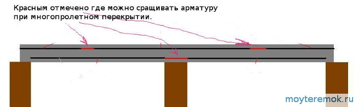
Places where it is possible to break-increase reinforcement are also determined. On the floor of the foundation (we have a single-span floor), on one half of the house F12 reinforcement (span 3.4m), and on the other F14 (span 4.4m).
But above the first floor, the reinforcement in the beam parts above the large span passes F14 without breaks above the middle wall and, for good, should go a quarter of the next span, but mine is a little shorter. Above the smaller span there is reinforcement A500 Ф12 and tied with Ф14.
 Clamps from A500 F6 first go a quarter of the span on each side with a step of 200mm, then closer to the center with a step of 400mm (I saved a little). The overlap at the clamp should be at the top of the frame.
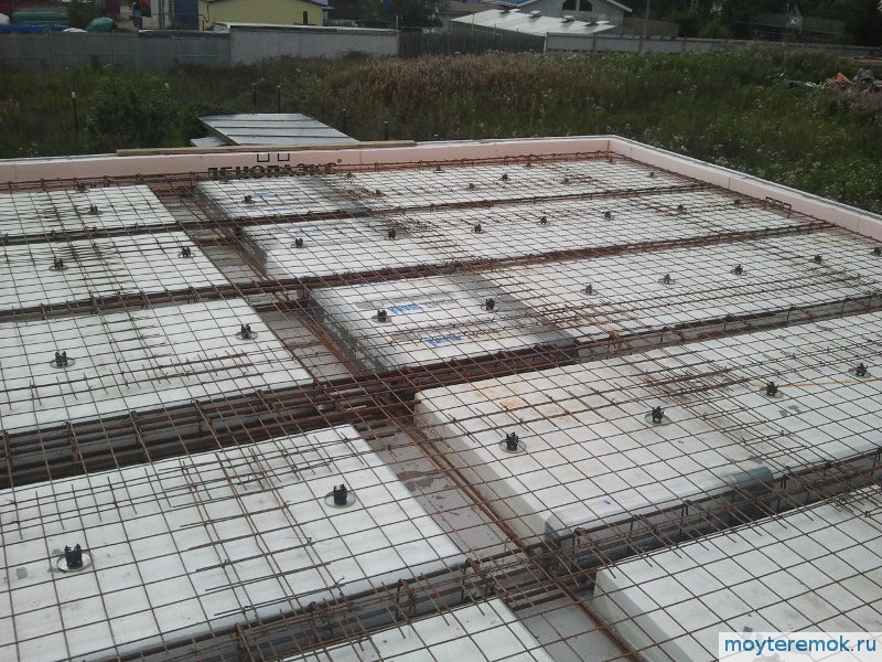
 Bay area. You can see the bay window, the F18 fittings of which are bent in both directions onto the wall and connected to the rest of the frame.
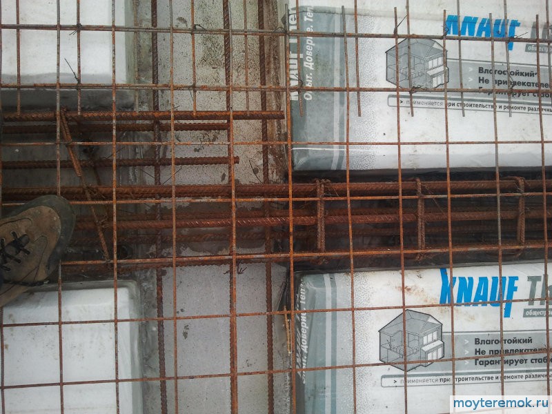
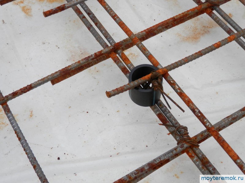
 So that the supports for the armature mesh made of Vr 5mm 100x100 do not dent into the foam, ordinary lids for cans are placed under them.
 On the ground, he made frames from reinforcement to cover the foundation. When overlapping the first floor, the frames were already knitted in place.
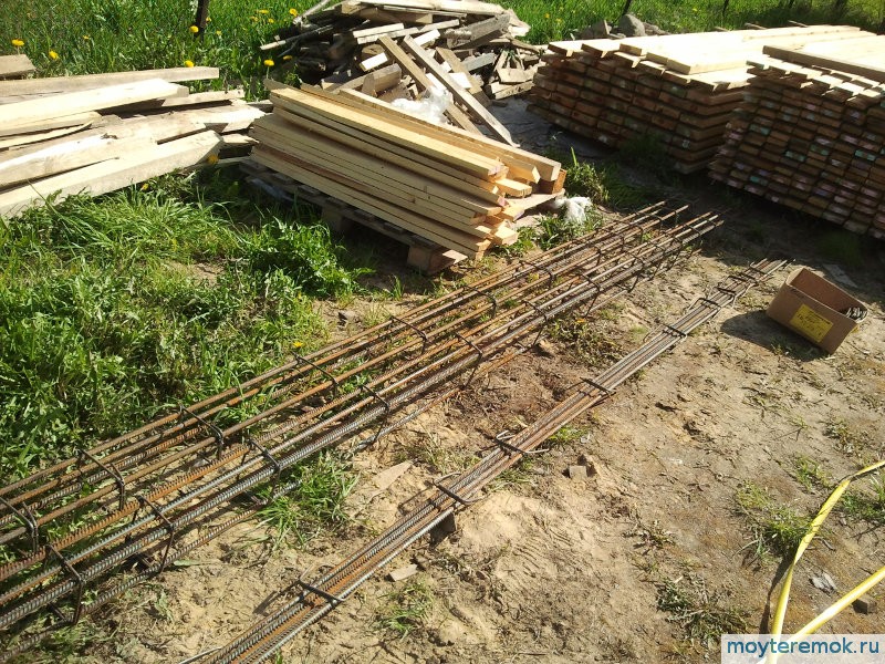 Quite a tedious task to knit frames for its overlap.
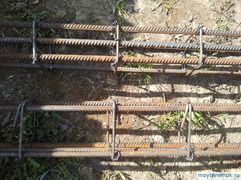 Frame close-up. All photos are clickable, click to enlarge.
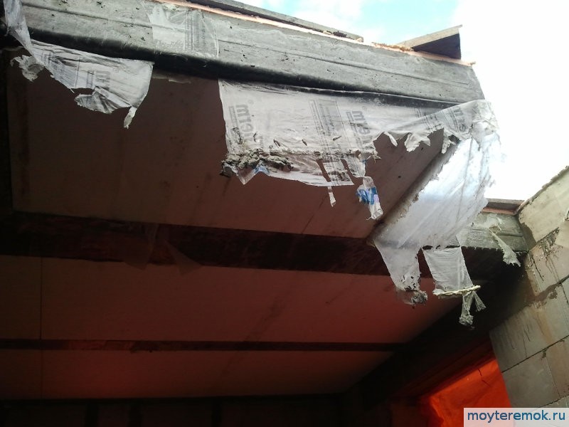
 The bay window beam on the other side goes on the wall for more than a meter and is linked to the general reinforcement. In order to avoid a cold bridge in the support zone, EPPS insulation 5 + 2 cm is used. Places with insulation are reinforced with boards during pouring.
 Double beams are made above the flight of stairs. That is, the reinforcement is twice as large and the width too. Like two ordinary beams side by side.
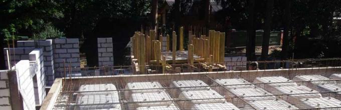
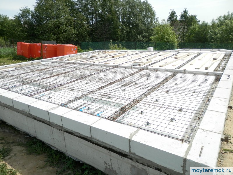
 Single-span ceiling above the foundation. You can just see the fixed formwork made of aerated concrete in the center of the inner tape of the grillage (foundation).
 Supporting the ceiling according to the calculation of 15cm. Although on such small spans more is possible (Winder recalculated).
 Styrofoam and reinforcement cages were laid out. A strong wind arose, so we had to throw boards. The boards were removed as the grid of the first layer was laid out.
 We raised the grid from Vr Ф5mm 1 by 2 meters, a cell 100x100mm to the second floor. There was no larger size at that time. It is more convenient to use a grid of 2m x 3m. We cut 1.3m x 3m and 0.7m x 3m. We lay 1.3m down, overlapping two ribs and between them, and put 0.7m up above the rib. That is, without scraps and without joints between the ribs.
They put boards so as not to tear the polyethylene over the foam.
 Reinforcement in the area of the flight of stairs with double ribs.
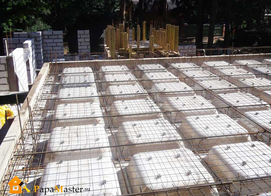
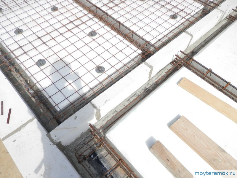
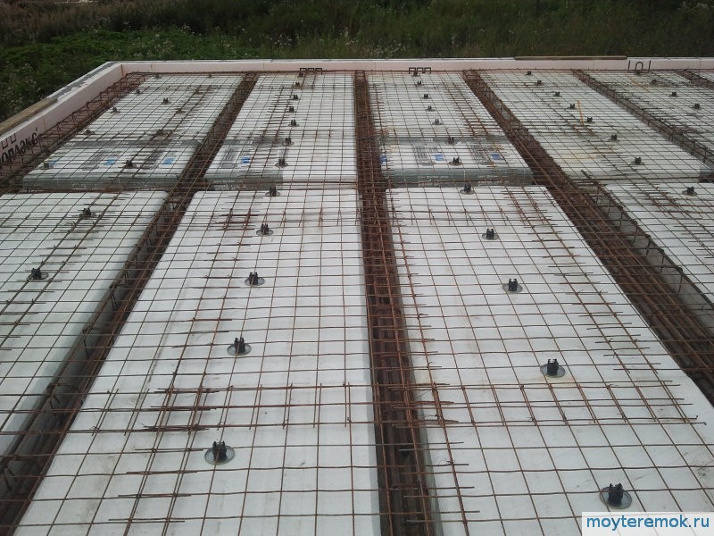 Solid mesh of the first row. The overlap was made at least one and a half cells almost everywhere, about two turned out. It is better to put more stands, otherwise the mass of concrete, even with lids, strongly presses into the foam.
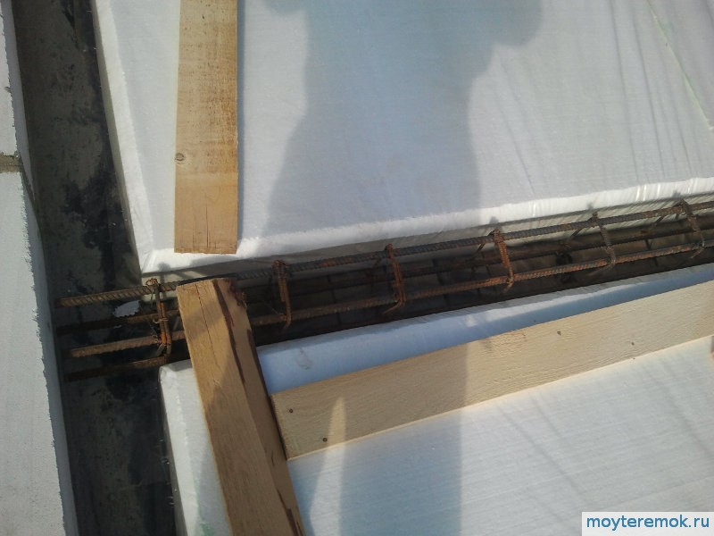
 Multi-span ceiling above the first floor, here the reinforcement cages of the ribs pass over the inner wall of the house. To ensure a gap between the grids, a 25 mm HDPE pipe was cut. Cheap and efficient.
Such rings are fastened with a knitting wire. We bend the piece of wire in half, grab the lower mesh bar, pass both ends through the HDPE ring and twist it over the upper mesh bar.
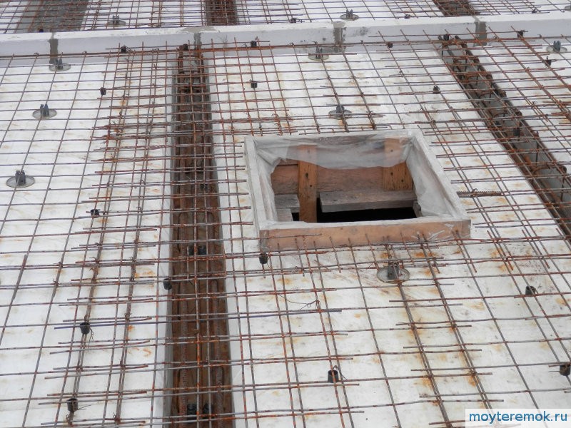
Manholes and openings can be made in a ribbed monolithic slab anywhere between the ribs.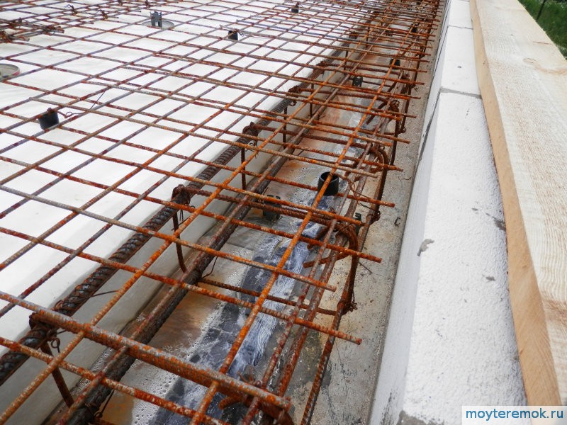 The perimeter reinforcement scheme depends on the distance left to the edge.
I have not yet found pictures with underfloor heating pipes, I will add them later.
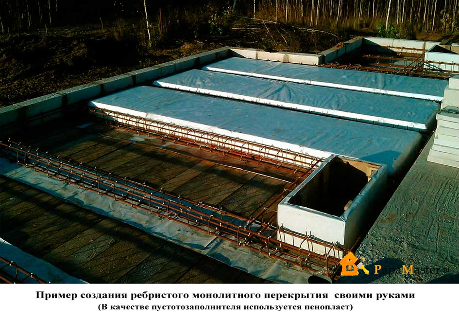
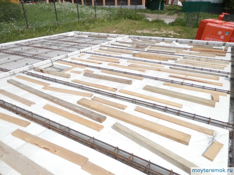
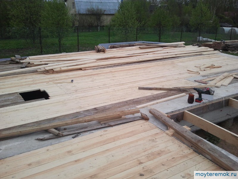
The formwork was done in the following way.
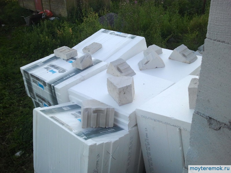 We bought Knauf foam plastic 10 and 5 cm thick.
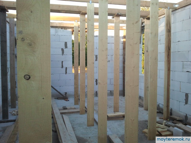
 Above the cellar pit, a beam of four 100x40 boards had to be fenced in order to rest the formwork on it.
When the foundation was covered, boards 150x40 were put on edge along the perimeter and attached to the grillage. I didn’t make holes in the grillage, it already had F8mm studs left over from fastening the formwork of the grillage itself.
On the second floor (first floor), such boards were attached to the walls with 120mm self-tapping screws. In one place of fastening, I screwed in two self-tapping screws at different angles.
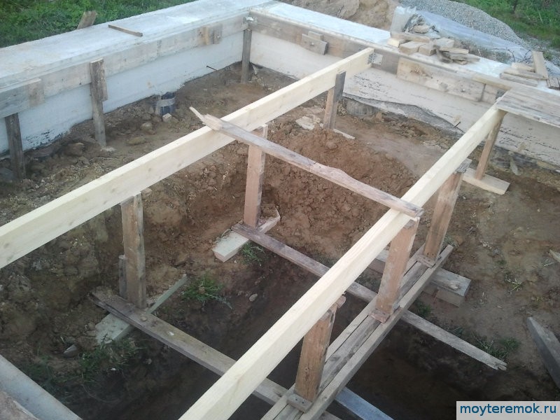 Then we put boards 150x40 on the edge, although such spans can be flat, so that they are under the edges of the future monolithic floor. We fastened them to steel corners of various formations, on average 100x90x100. The corners were fastened to white F6mm self-tapping screws, later to roofing screws and a bunch of others.
 So that the supports do not go away when pouring into the ground, they laid trimming boards under them.

 Struts in the underground.


 The first blocks of fixed formwork made of aerated concrete.
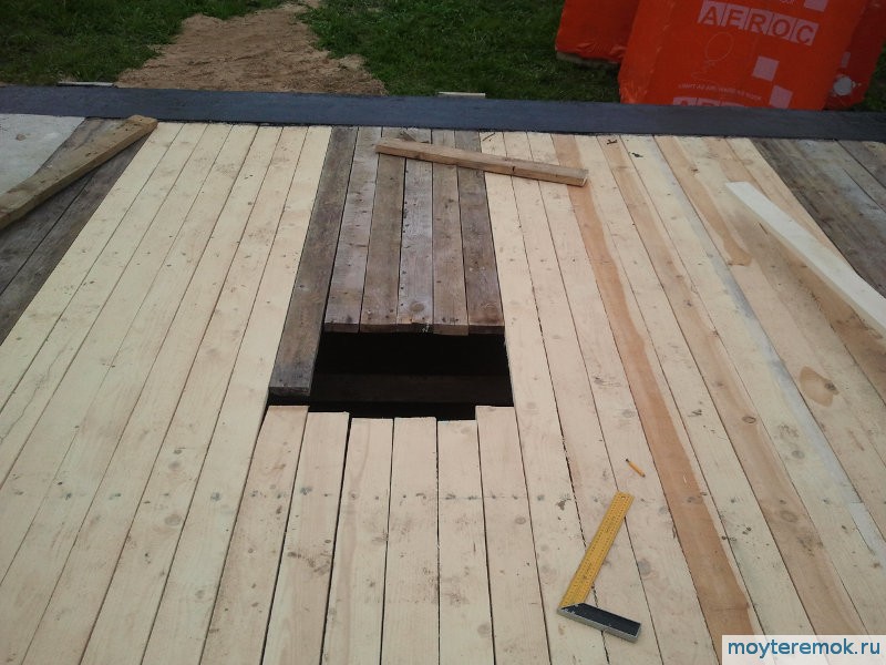 A hole in the formwork to pour the cellar floor slab. The filling was carried out simultaneously with the overlap.
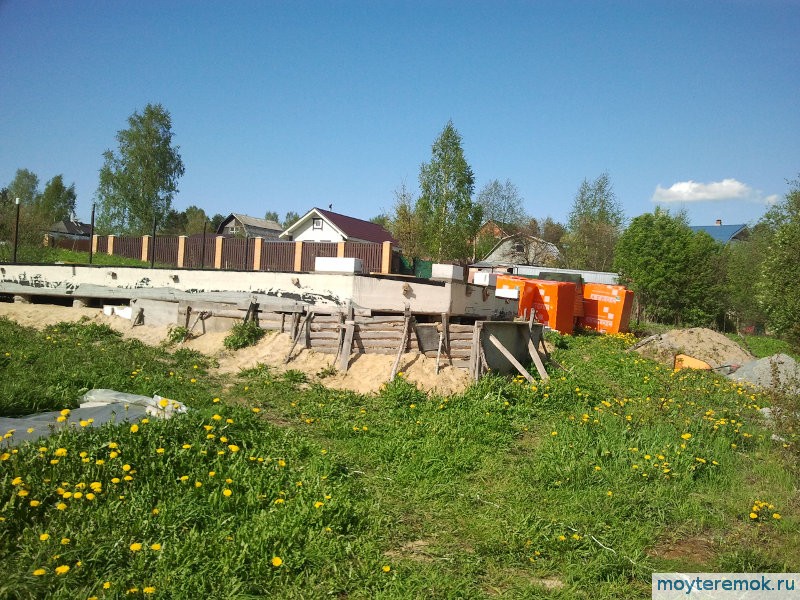
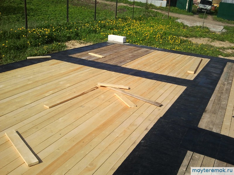
 The surface of the grillage (foundation) was first smeared with a bituminous primer, then the waterproofing Linocre from TechnoNIKOL was welded.


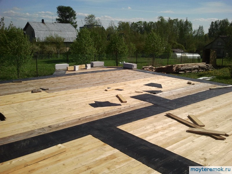
 On the middle part of the grillage (under the middle wall), sawn partition blocks 100x250x625 were placed in the middle 211 KZHBI Sertolovo D500 left over from building a small house, sawn side down. You can not try hard to saw off evenly, the solution levels everything.
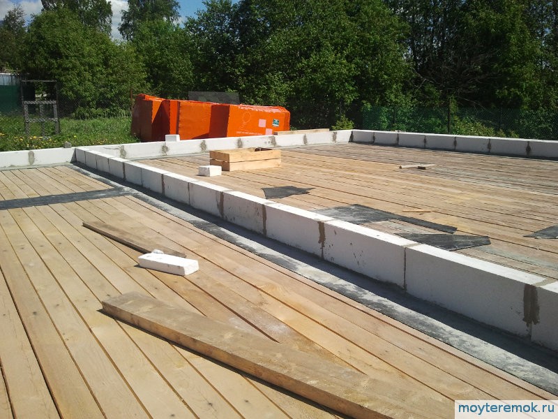
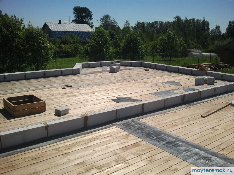
 During the construction of the ceiling above the grillage, a non-removable formwork of aerated concrete blocks was made around the perimeter. used Aeroc 250x200x625 D500. The block was inverted so that the height became 200. Together with a layer of cement-sand mortar, it turned out to be just about 21cm. Between themselves, the blocks were placed on Aeroc summer glue.
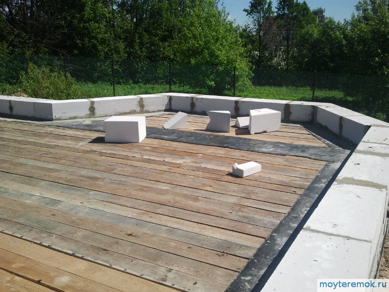
Above the first floor for a ribbed monolithic ceiling, a fixed formwork was also made from GB Aeroc 250x150x625 D400. The block did not turn over, i.e. formwork height was 25cm. After laying the formwork, a 50 mm extruded polystyrene foam insulation was glued to the mounting foam around the perimeter.
Also here we decided to use the option with a built-in water-heated floor (therefore, the height of the ceiling increases a little, namely, somewhere by the diameter of the pipe). According to the religion of classical screeds with a warm floor, this cannot be done. They share a large area expansion joints. According to the religion of the UWB foundations, it turns out possible. There, large areas of underfloor heating are poured along with the foundation slab.
In practice, simultaneous casting completely rolls. Insulation in the formwork also acts as a damper during thermal expansion of the floor concrete. Although, as practice shows (for some reason it does not confirm the theory), even without a damper nothing would have happened.
The cheap Chinese CMI proved to be excellent at work, turned out to be much more convenient than household Bosch and so far endures my loads. Then he took a CMI impact drill for a penny as a construction specialist. It is felt that something is not right in terms of comfort, but it looks brutal. Endures all my bullying
Offtopic drove, now to the point. The flooring was nailed with 70 nails. Above each edge, a nail. Remember that you still have to disassemble this design later.
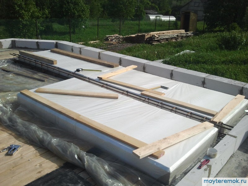
The formwork for the formation of ribs was almost completely taken over by my other half. Styrofoam was used for it Knauf with unclear characteristics (density). Two sheets of 100mm were laid and 50mm on it with a 20mm edge trimmed according to the instructions. Between the ribs, the width of the foam sheet is obtained, that is, 1 meter.
Styrofoam was not fastened to the formwork with anything and also between each other. It is held in place by polyethylene, which is generously attached to the wooden formwork with a stapler. Staples 8mm. In the future, the armored carcass will press it down with its weight.
They took a simple, not dense, cheap polyethylene. Partially used polyethylene from foam packaging.
During the work on the formwork, problems may arise. We got them :)
- Until the armoframe is assembled, it is necessary to put weighting materials (we used boards and GB trims) on polyethylene-styrofoam, otherwise the structure tries to fly away in strong winds.
- Birds break through polyethylene and crumble foam with terrible force. Zadolbalsya scotch tape the whole thing to lead to a more or less normal look. Hanging plastic plates. They are swayed in the wind, which slightly improves the situation, scaring away the birds.
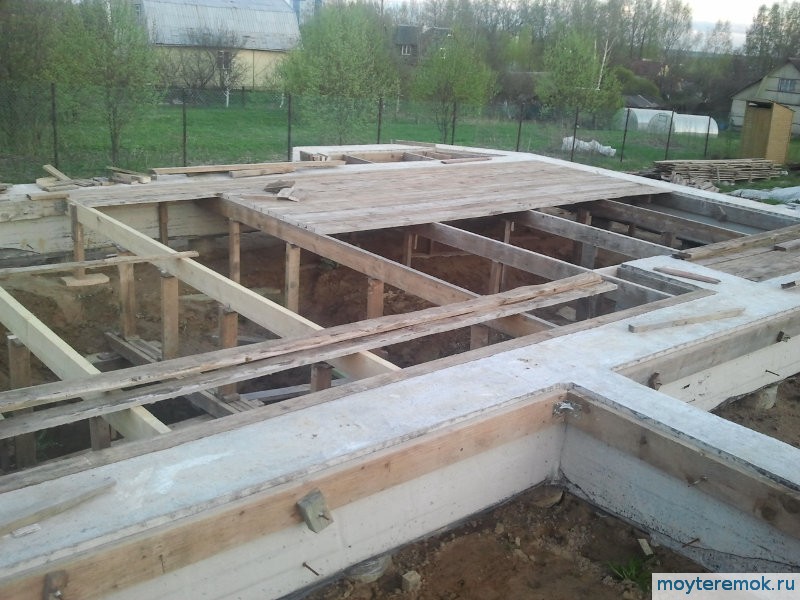
Filling the ceiling with concrete.
Before, I tried to stretch everything. Divide the work into parts. Now I am not a supporter of such methods and I do not advise you, of course, if there are no special circumstances. It happens, for example, that there is no way to deliver ready-mixed concrete, then you have to pour parts of self-mix.
We poured both ribbed monolithic floors with ready-mixed concrete M350(B25) from Pumik (mixer with integrated concrete pump). Although the floor is designed for the brand of concrete M200.
But firstly, a higher brand will level the jambs, if there were any - this is a margin of safety. Secondly, we have no time to wait a month until the concrete gains the required strength.
M350 concrete will gain the necessary strength to continue construction in a week. Thirdly, the manufacturer himself can mess up a little.
The first overlap was filled with a family contract: me, my wife and dad. It was very easy to pour from Pumik. I could easily manage with almost one hand. This is the professionalism of the driver who controlled the boom. He practically read my mind. This is not always the case. When we poured the grillage, the spruce trunk was held together. The driver turned on the pump strongly - he was in a hurry and did not look at work well.
Since there is a formwork above the inner wall, too, they took a six-meter forty and leveled the surface with it.
I called a friend to fill the second floor. This overlap is already multi-span, it took a long time to think how to fill it evenly. At first I wanted to pull the cable, but did not have time to do anything. As a result, just before pouring, I pulled a few nylon threads. Not really, but it turned out to be better than nothing.
Dad did not climb up. It was harder to hold the trunk than on the first floor, but still much easier than on the grillage. Given previous experience poured parts. They flooded the sector, turned off the pump, vibrated. Spread out the excess. As a rule, my wife went to smooth the top, and we continued to fill the next sector.
 When the slab hardened due to the fact that the fixed GB formwork was 2-3 cm higher than the slab surface, rainwater was collected on the slab. Holes were made for draining and tubes were inserted (pieces of pipe from a warm floor).
Formwork dismantling.
It took a long time to disassemble. Dismantled by large spans. The weight of the spans plays into the hands. A little swing and broads. The main thing is not to stand under it.
The surface is as smooth as glass. 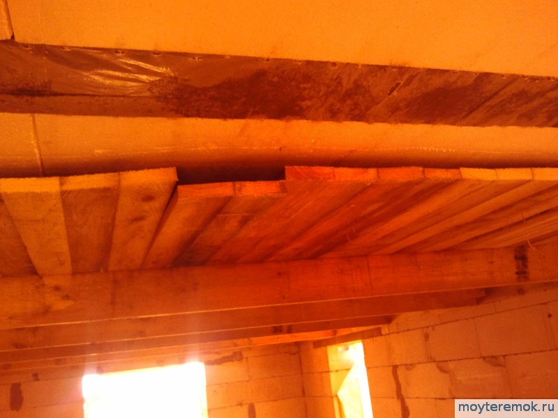
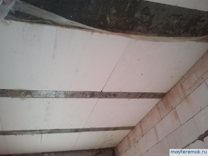
Ribbed ceiling in the area of the flight of stairs.  At first it is black, which was surprising, but it turns out that if you tear off the film, it dries and becomes the usual gray color.
FEDERAL AGENCY FOR EDUCATION
PERM STATE TECHNICAL UNIVERSITY
CONSTRUCTION FACULTY
DEPARTMENT OF BUILDING STRUCTURES
EXPLANATORY NOTE
To the course project
CALCULATION OF A MONOLITHIC RIBBED COVER
Perm, 2009
Introduction
A monolithic ribbed floor consists of a monolithic slab, secondary and main beams, monolithically interconnected.
The essence of a monolithic-ribbed floor is that, in order to save concrete, it is removed from the tension zone and is concentrated mainly in the compressed zone. In the tension zone, the concrete is kept only to accommodate the working tension reinforcement.
The monolithic slab runs along the short side as a multi-span continuous beam, rests on the secondary beams and is monolithically connected to them.
Secondary beams perceive the load from the monolithic slab and transfer it to the main beams, monolithically connected to them.
The main beams are supported by columns and exterior walls.
1. Choosing an economical option
1.1 Monolithic floor with main beams along the building
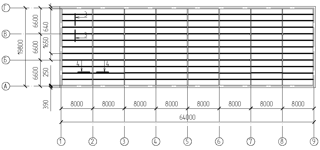
Secondary beam span l wb =6600 mm; main beam span l gb =8000 mm. We take the height of the plate h pl =80 mm For q vr =11,5 kN/m 2 and step of secondary beams 1600 mm (rice. 1).
Rice. 1. "Scheme in terms of monolithic-ribbed floor"
. ,accept the height of the secondary beam
take the height of the main beam
.
Rice. 2 “Section 1–1. Main beam»

Rice. 3 “Section 2–2. Secondary Beam"
Then the weight of all main beams:
.The total weight of all concrete required for a monolithic ribbed slab, with the main beams located along the building:
.3.2 Monolithic floor with main beams across the building
Secondary beam span l wb =8000 mm; main beam span l gb =6600 mm. We take the height of the plate h pl =80 mm For q vr =11,5 kN/m 2 and step of secondary beams 1650 mm (rice. 4).
Rice. 4 "Scheme in terms of monolithic-ribbed floor"
1. Determine the weight of concrete required per slab:
.2. Determine the weight of concrete required for the secondary beam:
Determine the required height of the secondary beam:
,accept the height of the secondary beam
Determine the required width of the secondary beam:
,accept the height of the secondary beam
Then the weight of all secondary beams:
.2. Determine the weight of concrete required for the main beams:
Determine the required height of the main beam:
,take the height of the main beam
.Determine the required width of the main beam:
,
take the height of the main beam

Rice. 5 “Section 3–3. Secondary Beam"
Rice. 6 “Section 4–4. Main beam»
Then the weight of all main beams:
.The total weight of all concrete required for a monolithic ribbed slab, with the main beams located across the building:
., then for the final version for calculation we take a monolithic ribbed slab with main beams located along the building.
2. Calculation of a monolithic slab
2.1 Collection of loads on the slab
Table 3
| Name |
Reliability factor |
||
| A) floor construction |
|||
| 1. URSA boards , |
|||
| 2. glassine 1 layer |
|||
| 3. Cement-sand screed , |
|||
| , |
|||
| B) Self weight of the slab |
|||
We select a strip 1 m wide. Then the calculated load
.rice. 7.

Rice. 7. “Longitudinal section of the slab. Settlement scheme»
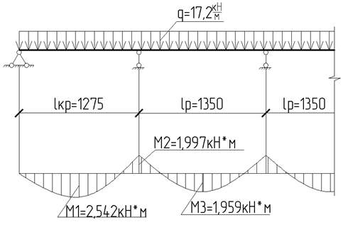
The slab is calculated as a multi-span continuous beam, on which a uniformly distributed load acts (Fig. 7). The calculated span is taken equal to: extreme - the distance from the center of the support to the edge of the secondary beam, the middle one - the distance between the secondary beams:
We determine the largest moments that occur in the slab:
 ;
;
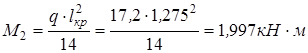 ;
;
 .
.
4.2 Selection of reinforcement in the middle span
To calculate the slab, we select a strip 1 m wide. Then the calculated section of the slab will be as follows ( rice. 8).
As a first approximation, I accept reinforcement B500 with a diameter of 6 mm.

Rice. 8. "Calculated section of the plate"
, is the width of the design section, is the design height of the section; - coefficient taking into account the duration of the load. ,According to the assortment, we select the diameter of the reinforcement and the number of rods: n \u003d 7 reinforcement rods B500 with a diameter of d \u003d 4 mm, for which
Determine the pitch of the rods:
The working rods are laid out along the plate in accordance with the moment diagram. We select transverse rods constructively: reinforcement rods B500 with a diameter d =3 mm in increments of 300 mm.
We finally accept the C-1 grid:
Rice. 9 Grid С-1
4.3 Selection of reinforcement in the last span
In the last span, in addition to the C-1 grid, we additionally roll out the C-2 grid across the plate.
To calculate the slab, we select a strip 1 m wide. As a first approximation, I accept B500 reinforcement with a diameter of 6 mm.
.Determine the required reinforcement area:
According to the assortment, we select the diameter of the reinforcement and the number of rods: n = 4 reinforcement rods B500 with a diameter of d = 3 mm, for which
We accept the step of the rods structurally 200 mm.
We lay out the working rods across the plate.
We select longitudinal rods constructively: reinforcement rods B500 with a diameter d =3 mm in increments of 300 mm.
We finally accept the C-2 grid:
Rice. 10 Grid С-2
3. Calculation of the secondary beam
3.1 Collection of loads on the secondary beam
Table 4
| Name |
Reliability factor |
||
| A) floor construction |
|||
| 1. URSA boards , |
|||
| 2. glassine 1 layer |
|||
| 3. Cement-sand screed , |
|||
| 4. ceramic tiles , |
|||
| B) Floor slab weight |
|||
| 3. Self weight of the secondary beam  |
) | ||
We build the envelope diagrams of the moments according to the formulas:
; .
The obtained moment values are summarized in Table 5.
Table 5
| end span |
|||||
| middle span |
|||||
The design scheme of the overlap is presented on rice. eleven.
Rice. 11. "Design scheme of overlap"
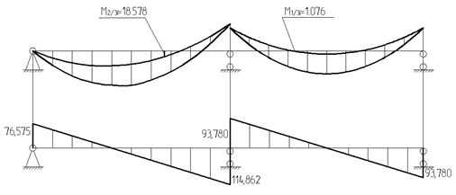
Rice. 12. "Enveloping diagrams of moments, diagram of transverse forces"
The secondary beam is calculated as a continuous multi-span beam with uniformly distributed load. The calculated span is taken equal to: extreme - from the center of gravity of the support to the edge of the rib of the main beam; middle - clear distance between the ribs of the main beams.
We determine the largest moments that occur in the secondary beam:
;;
 .
.
3.2 Selection of bottom reinforcement in the last span
This article is a discussion on the topic of calculation of monolithic reinforced concrete structures in various calculation systems.
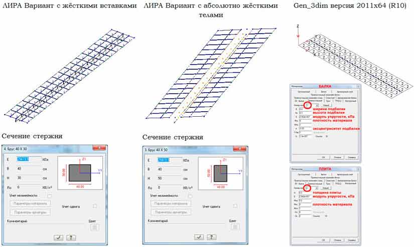
Many designers faced the problem of calculating monolithic reinforced concrete slabs reinforced with beams (other names: monolithic ribbed slab, beams with a T-section, monolithic beam slab, etc.). There are no problems with a beam on two supports - everything is simple here: design scheme, loads, formulas, forces, fittings, cracks. Problems arise when such a beam (ribbed slab) needs to be modeled in a finite element model of a building frame. A lot of people think about this, I did too. To obtain objective data, I decided to calculate such a design in two different software systems: LIRA and MicroFe.
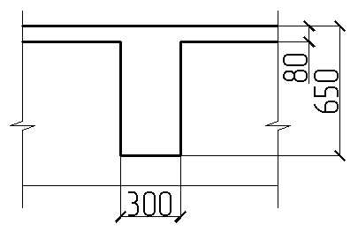
Initial data for the task: Beam span 9 m. Supports - rigid pinching from both sides. For the purity of the experiment, the own weight is not taken into account. Modulus of elasticity of the material 29420 MPa Load - distributed over the top of the plate 1 t/m 2 . The cross section is shown in the figure
A few words about the simulation of this design in software systems. Let's start with PC LIRA SAPR. If you read the designers' forums, then almost everywhere you will find tips to model a beam (rod) in the plane of the slab, and then set its eccentricity using rigid inserts. At the same time, the official technical support of LIRA SAPR recommends setting the beam below the plane of the slab, and, most importantly, removing the section of the slab above the rod with a width equal to the width of the rib, so that there is no double counting of concrete when calculating strength and selecting reinforcement. Thus, the beam and the slab live, as it were, separately from each other. This is eliminated by introducing absolutely rigid bodies (ARBs) in each node triangle (slab-beam-slab). The method is quite time-consuming, because AZT is introduced separately for each triple of nodes. As a result, the structure was modeled in SP LIRA in two ways: with rigid inserts and rigid bodies.
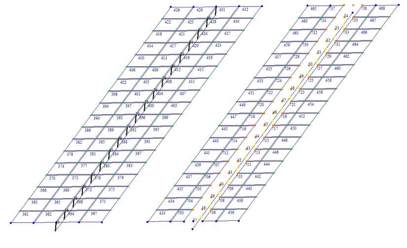
In the MicroFe program, the structure was modeled using elements of “sub-beams”. The breakdown of the slab part into finite elements in each calculation model was set the same - 0.5x0.5 m. The main results of the calculation are presented below. Own weight was not taken into account in the calculation.
General view of the design scheme
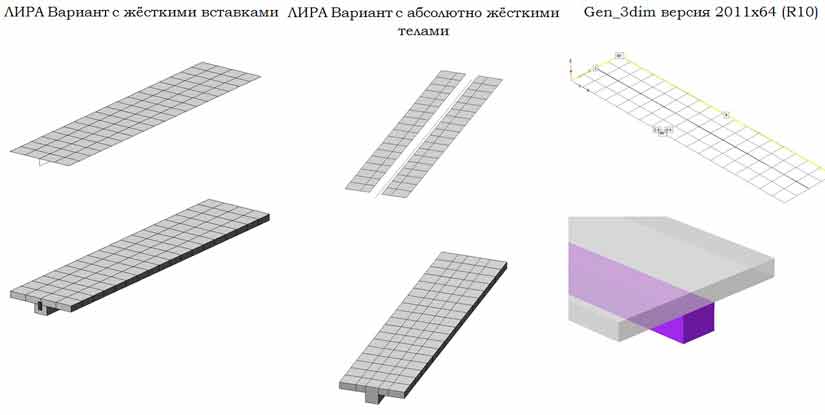
Rigidity of finite elements. The thickness of the slab in all cases was equal to the thickness of the section flange.
The first check is the total reaction of the supports, which should be equal to the sum of the loads applied to the structure. In all three tasks, it turned out to be equal to 720 kN = 72 tf.