The question is how to do it right reinforcement of columns made of concrete, primarily worries those people who lead building a house with your own hands without a professionally designed project. Surely this is not the most the best option building a dwelling, but so many build. They build by consulting with experienced builders or trying to find necessary information in the Internet. Tips - tips, but it is best to order the calculation of columns in a design organization. True, not everyone has such an opportunity. And among the large amount of information on this topic available on the Internet, almost all inexperienced people are looking not for formulas for calculating monolithic columns, but for simple advice: do it. To help such people, I will try to give the maximum amount of information, using standard schemes as an example. column reinforcement For country houses medium area.
Anticipating the comments of professional builders regarding the content of this article due to deviation from the rule, it is necessary to perform calculations, I want to ask them this. If, according to the schematic design of the future house, on the first floor in the middle of the building there will be only one or two (with spans of less than 6 meters), and on the monolithic floor of the first floor there will be attic floor, why fool people with calculations, especially if they do not have the opportunity to contact design organization? It is quite another matter if the constructive scheme of the future house will consist of monolithic columns and monolithic floor, and the walls will be built of light materials. In this case, the calculation of columns and floors is required!
Correct reinforcement of columns- the guarantee of the strength of the whole house. At the same time, you should not reinforce monolithic columns, using the common phrase that the more metal, the stronger the structure. In addition, the location of the main and mounting reinforcement in the column frame has a decisive influence on the stability of this structure.
The cross section of a monolithic column depends on the total load acting on it. Most often, a section of 400x400 mm is used, although, according to the results of calculations, it is possible to install monolithic columns with a section of 300x300 mm. By the way, the first section coincides in size with the parameters of a brick column with a thickness of 1 ½ bricks, but a monolithic column has greater strength. Therefore, I suggest that you consider the reinforcement of a concrete column of just such a section.
The standard reinforcement scheme of a monolithic column consists of four vertical rods of the main, working reinforcement Ø 14-16 mm A 400C, which is connected into a single structure using mounting reinforcement Ø 6 mm A 240C.
In order not to violate the properties of the reinforcing bars at the points of their connection with other reinforcement, which inevitably occurs as a result of welding, it is better to “tie” the column reinforcement frame with a knitting wire Ø 1-1.2 mm. In addition, this method is more acceptable for those who do not have experience in performing welding work. To facilitate the knitting of the reinforcing cage, you can make a simple hook from Ø 6 mm wire. But before the direct assembly of the column frame, its main working rods need to be given a certain shape, and frames - clamps should be made from mounting fittings, which is quite easy to do using a simple bending device.
Main reinforcement in the column
Depending on the design scheme of your future home and the location of the columns, as well as,
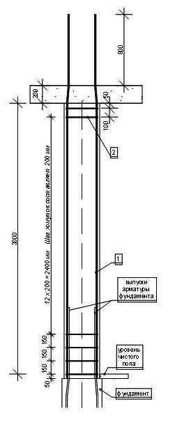
Accordingly, the load acting on them changes not only the diameter of the main reinforcement, but also its shape. So, if the columns in your house will be not only on the first, but also on the second floor, then the length of the rods of the first floor column is determined taking into account the following values:
- Distance from the top of the foundation under the column to the level of the finished floor;
- Floor height (from the level of the finished floor to the bottom of the monolithic ceiling);
- The thickness of the monolithic floor;
- It is necessary to add 800 mm to the resulting sum of values - it is to this height that the rods should protrude above the monolithic ceiling for a reliable connection of the frames of the columns of the first and second floors.
In addition to such reinforcement protrusion, for reliable connection of the column frames to each other, the upper end of the bars of the lower column must have a bend, as shown in Scheme 1. The value of deviation from the main direction of the reinforcing bar corresponds to the diameter of the reinforcement of the column frame of the upper floor and is performed in the area that will be located in monolithic cover.
And one more detail. Tapered main bars should be installed so that the offset of each bar is directed towards the center of the column.
If in your house they will be located only on one floor and serve to support the monolithic ceiling, to provide additional connection between the frame of the monolithic ceiling and the column, the working rods in the upper part are bent, as shown in diagram 2. In this case, the length of the rods compared to the first calculation option is reduced by 400 mm. I will tell you about how the additional reinforcement of the frame of the monolithic floor is carried out at the place of support on the column in the next post.
Structural reinforcement of the column frame
As mentioned above, it is much easier to assemble the column frame if the structural (mounting) reinforcement is bent with frames or, as we say, with clamps. The size of such a frame made of reinforcement Ø 6 mm A 240C for a column with a section of 400 x 400 mm is determined taking into account the fact that the protective layer of concrete around the frame must be at least 20 mm on each side. Based on this, the length of one side of such a collar frame should be no more than 360 mm on the outside. In addition, special bends are made along the edges of the workpiece, which provide a collar on one of the main rods in one frame. The inner diameter of such bends must not be less than the diameter of the main reinforcement.
The location of the mounting fittings (clamps) along the length of the frame is uneven. Optimal location clamps with an indication of the step size is shown in diagram 1. I also want to draw your attention to the lowest clamps installed at the bottom of the column frame. Since in this zone of the column the outlets of the main reinforcement of the foundation and the main frame of the column are connected, the rods in the lower part will be double. Therefore, the length of the bends along the edges of the clamp blank should be
more than shown in diagram 3 in order to capture two rods at once. In addition, it is necessary to install lower clamps from mounting fittings Ø 6 mm A 240C not during the manufacture of the column frame, but after its connection with the reinforcing outlets of the foundation. IN otherwise, in a critical situation with a strong side impact, ready monolithic column may just fall off as shown in the photo. Judging by the releases of foundation reinforcement, they are of insufficient length, and the clamps installed on the column frame were simply removed from such short releases.
n this - the number of floors in the building;
p n sn - normative load from snow per 1 m 2 of coverage, can be taken as for the Donetsk region p n sn= 1.5 kN/m2;
h count - the size of the side section of the column (m), adopted during the layout of the floor (see section 2 of the "Instructions");
ρ reinforced concrete \u003d 25 kN / m 3 - density of reinforced concrete;
1.1, 1.2, 1.04 - load safety factors (depending on its type);
H this- floor height (m) (indicated in the task for the course project).
The full load consists of permanent and temporary parts, which can be calculated as:
- temporary part loads:
- continuous part loads:
 .
.
^
Column Flexibility
, Where  - the estimated length of the column, which is assigned depending on the method of fixing its ends. For example, if the building without basement
, then the column of the first floor is partially fixed in the foundation and hinged at the floor level (more precisely, at the level of the bottom of the crossbar, which is welded to the column console and prevents the column from deforming). In this case, the value of the estimated length of the column is equal to
- the estimated length of the column, which is assigned depending on the method of fixing its ends. For example, if the building without basement
, then the column of the first floor is partially fixed in the foundation and hinged at the floor level (more precisely, at the level of the bottom of the crossbar, which is welded to the column console and prevents the column from deforming). In this case, the value of the estimated length of the column is equal to  , Where H 1
- the distance from the bottom of the crossbar of the first floor to the upper edge of the foundation, that is H 1
= H this + 0,15 -
h rig -
h pl .
, Where H 1
- the distance from the bottom of the crossbar of the first floor to the upper edge of the foundation, that is H 1
= H this + 0,15 -
h rig -
h pl .
If the building provides basement
, then the first floor column rests on the basement column, and has hinge fastening at the level of the bottom of both floors that border it. Then the estimated length of the column in this version of the building is:  .
.
The student at this stage must decide on the presence or absence of a basement in his building and calculate the corresponding value of flexibility .
But you have to remember
that the decision made here affects the design of the column when drawing it. Namely: in order to make joints of adjacent columns, it is necessary to have lower and upper metal embedded parts (this applies to columns intermediate in height of the building). If the column of the first floor is installed in the foundation (that is, the building no cellar), then such an embedded part in its lower part should not be provided. Therefore, this circumstance must be taken into account when developing working drawing of the column.
^
4.3.2. Column materials
Concrete class
for the column should be taken not lower than B15, and for heavily loaded columns (that is, when N=1500
2000 kN)- in the range IN 20
B40.
For the accepted class of concrete from the Norms, write out the design resistance R b taking into account the coefficient b2(its value should be taken the same as in the slab and crossbar, because for the structures of the entire building the nature of the load is the same).
For longitudinal reinforcement A-III or A-II; from write out the value of the design resistance of steel R sc .
For transverse reinforcement
columns should adopt steel grade A-I
or VR-I.
^
4.3.3. Choice of design scheme and calculation of the column body
columns multi-storey buildings experience eccentric compression, therefore, forces arise in the sections of the columns M, N, Q.
IN course project when calculating the column, it is allowed not to take into account the moment that occurs in it as in a frame element.
The calculation of the strength of the body of the column should be performed as for a conditionally compressed element according to the algorithm given in Table 4.3.
Table 4.3
Determination of the section dimensions and area of the working longitudinal reinforcement of the column as in a conditionally centrally compressed element
| № p/n | Algorithm | ^ Explanations, references |
|
| 1 | 2 | 3 |
|
| 1 | Determine the required concrete area of the column section from the strength condition:
| µ 1 - reinforcement coefficient, which is recommended to be taken as a first approximation µ 1 = 0.01 (which corresponds to the content of reinforcement in the section within 1% of the concrete area). |
|
| 2 | Determine the required dimensions of the column section:
| If you want to keep the previously accepted dimensions of the column section, you should return to step 1 of the algorithm and vary the classes of concrete and reinforcement in order to obtain the required dimensions of the column section here. |
|
| 3 | Assign the dimensions of the column section  taking into account the requirements of unification. taking into account the requirements of unification. | According to the requirements of unification, the size hkol must be a multiple of 50 mm if it does not exceed 300 mm, and a multiple of 100 mm for sizes from 300 to 500 mm; with a size of more than 600 mm, it is assigned a multiple of 200 mm. The dimensions of the column section adopted here are considered final at this stage and are used in further calculations. |
|
 (m 2
)
(m 2
)Continuation of the table. 4.3.
| 1 | 2 | 3 |
| 4 | Accept working condition coefficient m for section. | Accept m = 1 at |
| 5 | Calculate factor :
| Here: µ 1 adopted at this stage of the calculation, the coefficient of reinforcement (see paragraph 1 of the algorithm); b
,
r
coefficients depending on the flexibility of the column
and relationships |
| 6 | Determine, as a first approximation, the required area of the longitudinal reinforcement of the column from the strength condition:
|  area of the concrete section for the dimensions of the section adopted in paragraph 3 of the algorithm. area of the concrete section for the dimensions of the section adopted in paragraph 3 of the algorithm. |
| 7 | According to the assortment of reinforcement, take the required number of rods so that their total area  provided provided  . . | Fittings 412 of the corresponding class should be adopted. Give the scheme of reinforcement of the column according to fig. 4.10. |
| 8 | Calculate the final value of the percentage of reinforcement for the longitudinal reinforcement at this stage of the approximation:
| ^ The optimal value of the percentage of reinforcement for compressed elements is (13)%. |
| 9 | Compare the percentage of reinforcement adopted at the beginning of this approximation step µ 1 , with final µ con . Note. The calculation method presented here refers to the so-called method of successive approximations. | If these values are in the ratio below, then the calculation of the longitudinal reinforcement is completed: 0.7 i i con 1.3 i . If the given ratio not fulfilled , one more stage of approximation should be performed, taking a new value of the percentage of reinforcement equal to 2
=0.5(
1
+
1
con
)
and repeat the calculation, starting from step 1 of the algorithm until the above ratio is satisfied. |
| 10 | End of calculation. |

 .
. (see clause 4.3.1); are determined according to the table. 1, given in the Appendix of the method of guidance.
^
4.3.4. Transverse reinforcement of the column
The purpose of transverse reinforcement in compressed elements is to ensure the stability of compressed longitudinal rods. Therefore, the distance ″ S
″ between the transverse bars in the column is assigned based on ultimate flexibility requirementslongitudinal rods
within the limits between their anchoring points, i.e. between connecting cross bars. These requirements look like: S ≤ .
Where  - the smallest diameter of the longitudinal rods in the section (if several different diameters are used).
Step "S" transverse rods for the column take a multiple of 50mm.
Diameter transverse rods should be taken based on weldability requirements, excluding arson of reinforcement during welding, namely: d hom [ d prod /3; 4mm].
Provide a sketch of the reinforcement of the column, on which indicate the accepted parameters of the longitudinal and transverse reinforcement of the section (according to Fig. 4.10). 
Rice. 4.10. Column reinforcement sketch
^
4.3.5. Column console design
In the course project, it is recommended to take the so-called short
reinforced concrete console, i.e. one that meets the requirement:  (Fig. 4.11).
Purpose of calculation consists in determining the dimensions of the section and reinforcement of the console, which would ensure its strength.
The calculation of the console should be performed according to the algorithm of Table. 4.4, which is drawn up in accordance with the requirements of Norms.
Table 4.4.
Calculation of a short reinforced concrete column console
| № p/n | Algorithm | ^ Explanations, references |
| 1 | 2 | 3 |
| 1 | Determination of the estimated length of the platform for supporting the crossbar  , which provides the strength of the concrete console for crushing: , which provides the strength of the concrete console for crushing:
| Q - bolt pressure on the console, which is equal to the maximum transverse force on the support ″ Calculate leverage |
| 9 | Appointment of the longitudinal reinforcement of the console (see explanation on the right of the table). | By value  required from the assortment to select the necessary reinforcement (1225) mm in the amount of 2 required from the assortment to select the necessary reinforcement (1225) mm in the amount of 2  3 rods. Arrange them horizontally at a distance h 0
from the lower (compressed) edge of the console. Give a sketch of reinforcement (Fig. 4.11). 3 rods. Arrange them horizontally at a distance h 0
from the lower (compressed) edge of the console. Give a sketch of reinforcement (Fig. 4.11). |
| 10 | Choice of reinforcement scheme of the console with transverse reinforcement depending on the requirement:
| If requirement done, then reinforce the console with inclined clamps over the entire height according to the scheme of fig. 4.12-a. If requirement not done, the console is reinforced with horizontal clamps and bent rods according to the scheme of fig. 4.12-b.
|
| 11 | Assign the spacing of the transverse bars “S” (yokes and bent bars). | In this case, use the Norms. |
| 12 | Assign the diameter of the transverse rods by area:
| Here A sw (A s , inc ) total area of stirrups (bent rods) crossing top half line l , which connects the point of application of force Q on the console with the connection point of the inclined side of the console with the side of the column (see Fig. 4.12). At the same time, the number of clamps that provide the required area  should be found directly from the drawing of the console, made to a given scale, on which it is necessary to place all the transverse rods with a step S
(according to clause 11). should be found directly from the drawing of the console, made to a given scale, on which it is necessary to place all the transverse rods with a step S
(according to clause 11). It must be understood that in one plane of the clamps there can be at least two rods along the thickness of the console (most often 2-3 pcs.). |
 .
. - for clamps;
 - for bent rods.
 Continuation of the table. 4.4.
| 1 | 2 | 3 |
||||||||||||||||||||||||||||||||||||||||||||||||||
| In this case, the diameters of these rods should be taken to be 5 mm, also taking into account the requirements for weldability with the longitudinal rods of the console (see clause 4.3.4 of the "Guidelines"), and for bent rods also the requirements:
|
||||||||||||||||||||||||||||||||||||||||||||||||||||
| 13 | Checking the sufficiency of dimensions and transverse reinforcement of the console according to the condition of strength for the action of transverse force By inclined lane between the concentrated force and the support (Fig. 4.11): h 4 - horizontal clamps. ^ 4.3.6. Design of the joint of precast concrete columnsIn the course project, it is recommended to accept a welded joint of columns with end sheets and a centering gasket, that is, the so-called hinged joint (Fig. 4.13). Such a joint cannot perceive the moment. It is allowed to use a joint of another type with the appropriate calculation of its strength. The junction of columns is located at a distance of (0.5÷1.0) m from the floor level from the condition of convenience of its implementation. Due to the fact that the force from the column to the column is transmitted through the joint not over the entire sectional area of the column, but only through those elements of the joint that unite them (that is, through the end gasket and welds along the perimeter of the columns), the section of the column experiences the so-called local compression (collapse). In this case, the stresses in the local compression zone exceed those in the other sections along the height of the column. Therefore, the end sections of the column near the joint must be calculated for strength under local compression and reinforced | welded | meshes (the so-called indirect reinforcement), which increase the strength of concrete in local compression due to the "clip effect" that they create. Grids of indirect reinforcement should be placed in the amount of at least four with a step s = (60÷100) mm on the section of the column (counting from its end), the length of which is assumed to be 10 d (Here d - diameter of the longitudinal reinforcement of the column). These grids should be assigned before the start of the calculation in accordance with the design requirements of Norms. Before starting the calculation, it is also necessary to assign the dimensions of the centering spacer (the thickness should be 3÷5 mm and the dimensions in the plan equal to 1/3 of the size of the section of the column), the dimensions of the metal end sheets (the thickness is not less than 1012 mm, the dimensions in the plan - by 10÷15 mm less than the section of the column). The end sheets must have anchor rods that fix the position of the part in the concrete. In this case, the diameter and number of anchor rods of the part should be taken equal to the diameter and number of rods of the working longitudinal reinforcement of the column according to the calculation (see column calculation), since they replace this reinforcement in the places where it ends, somewhat short of the end sheets. Hence, calculation task the joint of the columns is as follows:
Table 4.5. Calculation of the joint of columns with a centering gasket
The end of the table. 4.5.
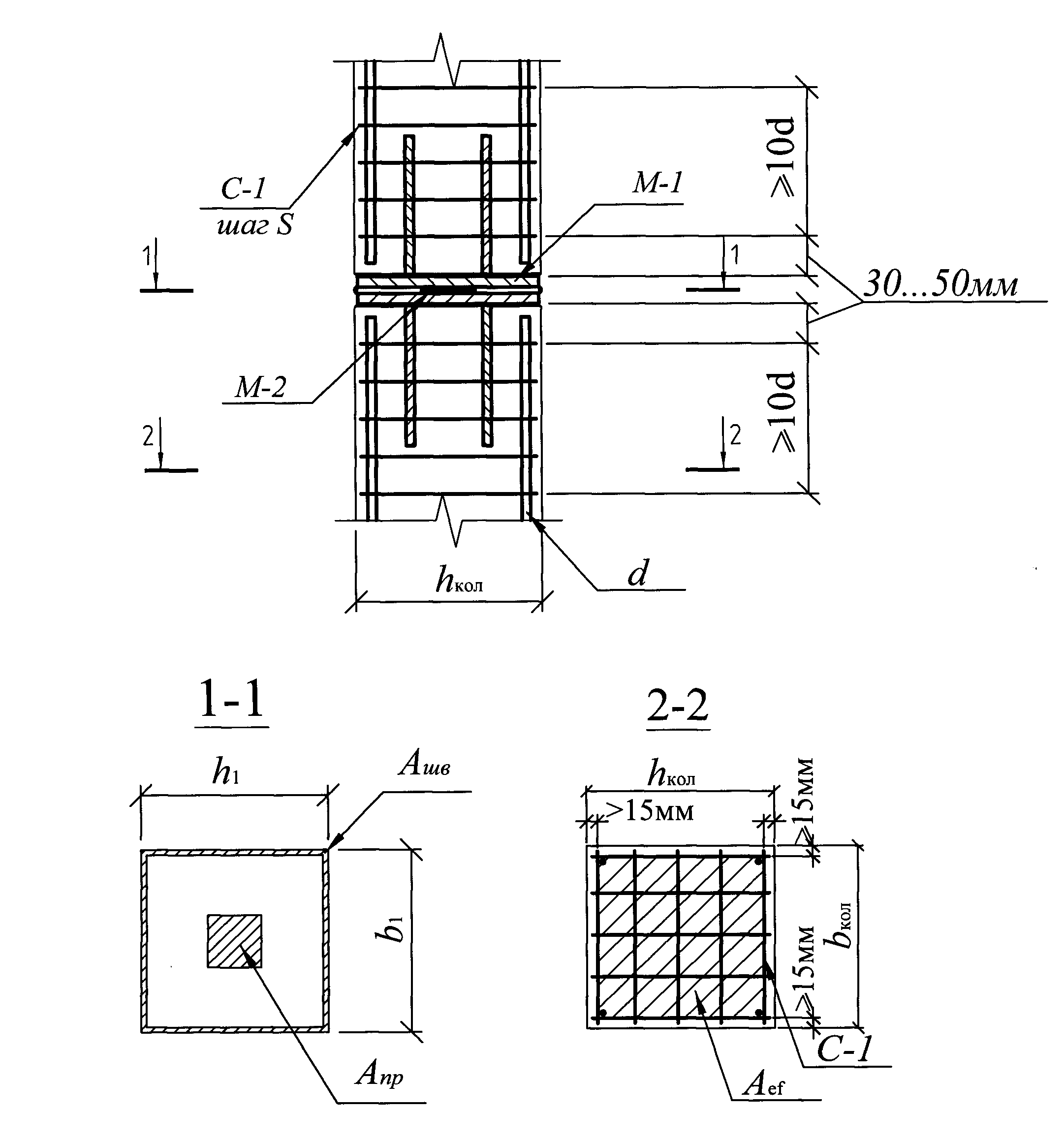 Rice. 4.13. To the calculation of the joint of columns for local compression. M-1- embedded part of the column; M-2– centering gasket; C-1– grid of indirect reinforcement; ^S- grid spacing in the end part of the column on the length of the section ≥ 10 d; d is the diameter of the longitudinal reinforcement of the column body; A ef- sectional area of concrete bounded by mesh contours C-1; A seam , A etc- area of concrete contact of columns under welded seams and centering gasket, respectively; h 1 , b 1 - respectively, the width and length of the end sheets of the part M-1. | |||||||||||||||||||||||||||||||||||||||||||||||||||
 .
.
 3.5.
3.5.
 .
. |
|
 ,
, .
.* * *
Design and calculation of plates
General provisions:
1.Class (grade) of concrete- not less than B30 (M400).
2.protective layer
3.Longitudinal reinforcement- A III. Minimum diameter d12mm. Step no more than 200 x 200 mm
4.Reinforcement percentage (for tension reinforcement)µ=0.5...2 (with a large percentage of reinforcement, a beam (caisson) floor is required).
5.Transverse reinforcement- d8A I (set if necessary according to the calculation), structural transverse reinforcement - in the form of studs in the nodes of the grid in a checkerboard pattern;
design transverse reinforcement (in places of concentrated loads) in the form of specially designed reinforcing products.
Construction instructions:
Minimum plate thickness h > 200 (160) mm;
The ratio of the span of the slab to the thickness L/h is not more than 30;
Reinforce the slab with meshes in the form of the main (background) and additional reinforcement (in places of significant bending moments). It is recommended to set the top and bottom background reinforcement equal. Under the lower design reinforcement, it is recommended to place a mesh 4ВрII - 100/100 (in the thickness of the protective layer), fasten the mesh with a knitting wire to the main reinforcement;
It is necessary to take into account the relative position of the bars of different directions of the same mesh - the bars of the working direction should be installed as close as possible to the edge of the slab ("Symmetric" reinforcement scheme);
If it is difficult to choose the working direction of the slab, a “skew-symmetric” reinforcement scheme is used;
The schemes of the mutual arrangement of the rods should be indicated on the working drawings.
Calculation instructions:
The safety factor (in addition to SNiP) should be assigned: for plates operating in one direction [k]=1.25, for plates operating in two directions [k]=1.15;
Console sections of slabs (balconies) should be calculated with a safety factor [k]=1.6.
* * *
Design and calculation of columns
General provisions:
1. Class (grade) of concrete- not less than B30 (M400).
2. protective layer- 35 mm (for underground structures - 40 mm).
3. Longitudinal reinforcement- A III. Minimum diameter d16mm.
4. Reinforcement percentage- µ=1...4 (for large percentages of reinforcement, installation of "rigid" reinforcement is required).
5. Transverse reinforcement- d8A I. Clamp spacing s=h/2, but not more than 15 d (with increasing s=100 mm in the supporting areas).
Construction instructions:
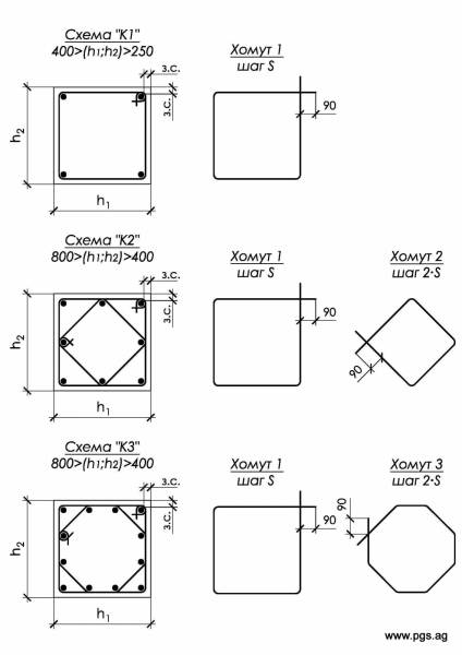
Minimum side size (h1;h2) > 300 mm;
The ratio of the length of the column to the width (flexibility) L/h no more than 20;
With the ratio of the sides of the section h1/h2=1...1.5, apply reinforcement schemes "K1", "K2", "K3".
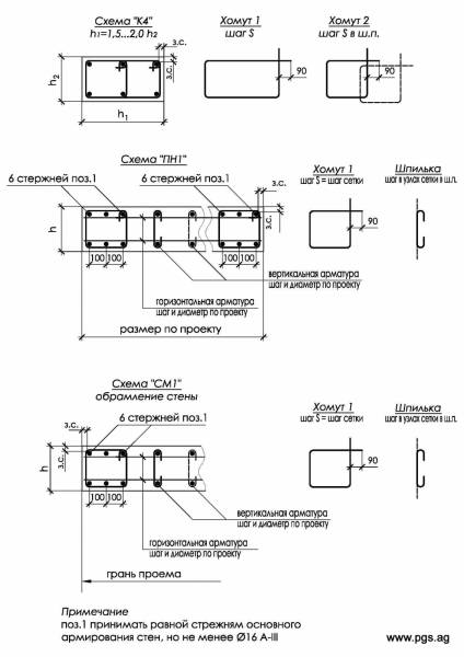
With the ratio of the sides of the section h1 / h2 = 1.5 ... 2, apply the “K4” reinforcement scheme, with a larger ratio, apply the pylon reinforcement scheme;
According to the height of the building, the reinforcement scheme of the columns is recommended to be taken constant. It is recommended to take the reinforcement scheme of the columns of the extreme row in the same way as the reinforcement of the columns of the middle row.
Calculation instructions:
The safety factor (in addition to SNiP) for the combined action of the longitudinal force (N) and bending moment (M) should be [k]=1.4; on the action of one longitudinal force take [k]=2;
- When assigning section dimensions, it is recommended to perceive the longitudinal force completely by the body of concrete;
When a longitudinal force with a small eccentricity e (e = M / N) acts on a column, the section of the column can only be calculated for the action of a longitudinal force, taking into account the coefficient of longitudinal bending (table below).
* * *
Design and calculation of walls and pylons
General provisions:
1. Class (grade) of concrete- not less than B22.5 (M300).
2. protective layer- 25 mm (for underground structures - 40 mm).
3. Longitudinal reinforcement- A III. Minimum diameter d12mm. Step no more than 250 x 250 mm
4. Reinforcement percentage- µ=0.5...2 (for large percentages of reinforcement, installation of "rigid" reinforcement is required).
5. Transverse reinforcement- d8A I. be placed in the form of hairpins in the nodes of the grid in a checkerboard pattern. along the faces of the walls (pylons) closed clamps are placed with a step s equal to the mesh step (in especially loaded cases, the step of the clamps is s=h/2).
Construction instructions:
Minimum wall thickness h > 200 (160) mm;
Ratio of wall height to thickness (flexibility) L/h no more than 30;
Reinforce pylons according to the "PN1" scheme, walls according to the "Sm1" scheme;
According to the height of the building, the wall reinforcement scheme is recommended to be taken constant.
Calculation instructions:
In view of the purpose of the sections from constructive (architectural) considerations, the safety factor is taken equal to [k]=1.0;
- If there are significant local loads on the section of the walls in the body of the wall, form a "hidden" column, or make a pilaster with reinforcement similar to the column.
* * *
Column reinforcement. The range and assortment of reinforcing bars produced at the metallurgical enterprises of the former USSR were formed under the influence of demand, oriented by the mass development of prefabricated reinforced concrete and in conditions practically isolated from the world market.
Until now, this circumstance, to a greater or lesser extent for various metallurgical enterprises, is reflected in the shortfall in profits associated with the production of obsolete types of rebar, with high cost and low competitiveness.
The requirements for rebar by builders (consumers) at an early stage in the development of reinforced concrete have remained relevant at the present time.
Taking into account the peculiarities of modern production and operation of reinforcing elements of prefabricated and monolithic reinforced concrete (frameworks, meshes, embedded parts, mounting loops, etc.), additional requirements for weldability, cold resistance, corrosion resistance were added to the basic requirements for strength, deformability and adhesion to concrete fittings, etc.
Due to the ever-increasing requirements for the quality of construction, the economic efficiency and reliability of the use of one or another type of reinforcing bar by the consumer are becoming fundamental for its implementation by the manufacturer.
At the early stage of rebar production, the main determinants of its consumer properties were the technical capabilities of steelmaking and rolling process equipment. Then the builders were forced to be content with the reinforcing products that the metallurgical industry produced.
Due to the rapid development of metallurgical production in last years almost all technological restrictions on the production of fittings were removed. At present, metallurgists are ready to produce those reinforcing products that can be effectively used in construction.
In accordance with SP 52-101-2003 for reinforcement reinforced concrete structures It is recommended to use the following types of fittings:
- hot-rolled smooth and periodic profile with a constant and variable height of the protrusions (annular and sickle-shaped profiles, respectively) with a diameter of 6-40 mm;
- thermomechanically hardened periodic profile with a constant and variable height of protrusions (annular and sickle-shaped) with a diameter of 6-40 mm:
- cold-formed periodic profile with a diameter of 3-12 mm.
The tensile strength class of reinforcement is indicated by:
- A - for hot-rolled and thermomechanically hardened reinforcement;
- B - for cold-formed reinforcement.
Tensile strength reinforcement classes A and B correspond to the guaranteed value of the yield strength (with rounding) with a security of at least 0.95, determined by the corresponding state standards or specifications.
IN necessary cases rebar is subject to requirements for additional quality indicators: weldability, ductility, adhesion to concrete, cold resistance, corrosion resistance, fatigue strength, etc.
When designing reinforced concrete structures, reinforcement can be used:
- smooth class A240 (A-I);
- periodic profile classes A300 (A-II), A400 (A-III, A400C), A500 (A500C, A500SP), B500 (Bp-I, B500C), where C is weldable, P is increased adhesion.
Until the 80s of the last century, the main volume of production and use in construction was reinforcement with a yield strength σ t =400 MPa. During the period 1991 - 1997, the main European countries switched to a single class of welded reinforcement of a periodic profile for unstressed reinforced concrete structures with a yield strength σ t \u003d 500 MPa.
For columns and racks operating in central compression, as a rule, a square section is taken, sometimes rectangular, round or annular. If the eccentricity is large (usually with eccentric compression), the cross section of the columns is assumed to be rectangular. In this case, the large sides of the rectangle are parallel to the axis, relative to which there is an eccentricity. Sections can also be tee or I-beam.
For standardization purposes, rectangular and square sections of columns are taken as multiples of 50 mm. For monolithic columns, a cross section of at least 250 mm is recommended.
Concrete for columns is used not lower than class B15 (C12 / 15), and for very loaded ones not lower than B25 (C20 / 25).
The columns are reinforced with longitudinal reinforcement bars with a diameter of ≥ 12 mm made of A400C or A500C steel and transverse bars or clamps made of A240C steel.
The dimensions of the cross sections should be taken such that the flexibility l0/r relative to any of the axes of the cross section does not exceed 120. The thickness of the concrete protective layer should be taken ≥ the diameter of the longitudinal reinforcement bars and not less than 20 mm. If strip, angle or shaped steel is used as longitudinal reinforcement (in columns with a rigid frame), the thickness of the protective layer is assumed to be ≥50 mm.
The clear distance between the vertical rebars placed vertically during concreting must be ≥ 50 mm. The distance between the bars of longitudinal reinforcement, located horizontally or at an angle during concreting, is taken to be ≥ 25 m for the reinforcement of the lower part of the section and ≥ 30 mm for the reinforcement of the upper part of the section. In addition, this distance in all cases is taken ≥ the largest diameter of the reinforcement.
Cross rods or clamps are installed without calculation, but subject to the following requirements:
- with a column cross-sectional width ≤ 400 mm and a number of longitudinal bars ≤ 4, flat welded frames without additional bars or single clamps are designed;
- with a cross-sectional width > 400 mm or a number of longitudinal rods > 4, additional rods are installed on one of the sides or double clamps are installed; - instead of double clamps, it is allowed to put connecting studs;
- bends of the clamps are provided at distances ≤ 400 mm along the width of the cross section of the element.
The design of knitted collars of columns should be such that the longitudinal rods (at least through one) are located at the bends of the clamps, and these bends - at a distance of no more than 400 mm along the width of the column section. With a face width of not more than 400 mm and the number of longitudinal rods for this face no more than four, it is allowed to cover all the longitudinal rods with one clamp.
The distance between the transverse reinforcement bars is assumed to be ≤ 15 d for knitted frames and ≤ 20 d for welded frames in order to prevent lateral buckling of the longitudinal reinforcement bars. In all cases, this distance is assumed to be ≤ 500 mm, where d is the smallest of the diameters of the longitudinal compressed rods.
In columns with a reinforcement ratio of longitudinal reinforcement > 3%, transverse rods or stirrups are placed at distances ≤ 10d and ≤ 300 mm.
The diameter of transverse reinforcement in welded frames is taken:
- 5-6 mm - with d = 14-20 mm of longitudinal rods;
- 8 mm - at d = 22-25 mm;
- 10 mm - at d = 28-32 mm;
- 12 mm - at d = 36-40 mm.
In knitted frames, the diameter of the clamps is taken ≥ 5 mm and ≥ 0.25d, in this case d is the largest diameter of the longitudinal reinforcement rods. As a rule, in the manufacture of knitted frames, clamps made of A240C class wire with a diameter of 6-8 mm are used.
If the project provides for embedded metal parts, then they should not protrude beyond the plane of the edges of the elements. Embedded parts must be welded to the working reinforcement or be securely anchored in concrete using special anchor hooks or rods.
Transverse reinforcement in columns is installed in order to:
1. Formation of spatial frameworks.
2. Prevention of bulging of the longitudinal bars.
3. Containment of transverse deformations of concrete.
Diameter of transverse reinforcement d is assigned from the condition of weldability with longitudinal reinforcing bars with a diameter D:
d³ 0.25 D= 0.25×36 = 9 mm. We accept transverse reinforcement Æ10 A 400.
The spacing of the transverse reinforcing bars should not exceed
s£20 D= 20x36 = 720 mm; s£500 mm. Accept s = 500 mm(multiply 50 mm).
To reinforce the end sections at the ends of the columns, we additionally install meshes of indirect reinforcement from reinforcement Æ8 A-I, mesh size 50´50 mm. We assign 5 grids with a step of 75 mm.
a b for longitudinal working reinforcement of the column (see Fig. 5.1) should be (clause 5.5 of SNiP):
4 not less than the diameter of the rod: a b ≥ D= 36 mm,
4 at least 20 mm : a b ≥ 20 mm.
Required distance from the outer face of the column to the center of gravity of the longitudinal reinforcement: A ³ a b + 0,5D= 36 + 0.5 36 = 54 mm. Accept a = 55 mm, Then
actual protective layer thickness: a b = A – 0,5D= 55 - 0.5 36 = 37 mm > 36 mm.
The thickness of the protective layer of concrete a bw for transverse reinforcement, the column should be (clause 5.5 of SNiP):
4 not less than the diameter of the rod: a bw ≥ d= 10 mm,
4 at least 15 mm : a bw ≥ 15 mm.
Actual cover thickness: a bw = a b – d= 37 – 10 = 27 mm > 15 mm.
Thus, the requirements for the size of the protective layer are met.
6. Calculation and design of the foundation
General considerations
· We design a separate monolithic shallow foundation for a column.
4 Basic concepts: edge of the foundation is its upper edge, foundation sole is the lower bound base- this is the soil under the sole of the foundation, foundation footing depth- this is the distance from the outer surface of the earth to the base of the foundation.
The depth of the foundation foot is assigned based on the engineering and geological conditions of the construction site, climatic influences on the upper layers of the soil (including the conditions of soil freezing), as well as the design features of the erected and neighboring structures and is (by assignment) df = 1,8 m.
· The floor of the 1st floor is carried out on the ground. Deepening the edge of the foundation relative to the floor level of the 1st floor: d 0 = 0,15 m.
foundation height: h f= df – d 0 = 1,80 – 0,15 = 1,65 m.
Calculated soil resistance of the base (as per assignment):
R 0 = 0,25 MPa = 250 kN/m 2 .
The average specific gravity of the foundation with soil on its ledges: g m = 20 kN/m 3 .
· The classes of concrete and reinforcement for the foundation are taken the same as for the crossbar of the floor (clause 4.1). Load duration factor g b 2 = 0,9.
Under the foundation, concrete preparation is provided with a thickness of 100 mm class concrete B3.5.
· The foundation for a column compressed with a random eccentricity perceives mainly only the longitudinal force, so it can be considered centrally loaded. Longitudinal forces at the level of the top of the foundation may be taken the same as at the floor level of the 1st floor (clause 2.4.4):
regulatory effort N k . n = 2826,3 kN; design force N k = 3164,2 kN.
Centrally loaded foundations are usually designed square in plan.
4 Eccentrically loaded columns and foundations are designed rectangular, with the wide side located in the plane of the bending moment.
· Calculation of the foundation consists of two stages. At the first of them, a calculation is carried out according to the bearing capacity of the foundation, as a result of which the area of \u200b\u200bthe sole of the foundation is determined A f. At the second stage, the calculation is carried out according to the bearing capacity of the foundation itself, on the basis of which the remaining dimensions of the foundation and the area of the working reinforcement are determined A s , f.