Although the factories reinforced concrete products produce a large number of finished products, yet sometimes you have to make a reinforced concrete floor beam or a reinforced concrete lintel yourself. And when building a house using fixed formwork, you simply cannot do without it. Almost everyone has seen builders-installers thrusting some kind of piece of iron into the formwork, and almost everyone knows that this is reinforcement that ensures the strength of the structure, that's just to determine the number and diameter of reinforcement or the cross section of hot-rolled profiles laid in reinforced concrete structures as fittings, only process engineers are good at it. Reinforced concrete structures, although they have been used for more than a hundred years, still remain a mystery to most people, more precisely, not the structures themselves, but the calculation of reinforced concrete structures. Let's try to lift the veil of mystery over this topic with an example of calculation reinforced concrete beam.
The calculation of any building structure in general and a reinforced concrete beam in particular consists of several stages. First, the geometric dimensions of the beam are determined.
Stage 1. Determining the length of the beam.
It is easiest to calculate the actual length of the beam. The main thing is that we know in advance the span that the beam should cover, and this is already a big deal. The span is the distance between the load-bearing walls for a floor beam or the width of the opening in the wall for a lintel. The span is the calculated length of the beam, the actual length of the beam will, of course, be greater. Since the beam cannot hang in the air (although real scientists have nevertheless achieved some success in antigravity), it means that the length of the beam must be greater than the span by the width of the support on the walls. And although all further calculations are made according to the calculated, and not according to the actual length of the beam, it is still necessary to determine the actual length of the beam. The width of the supports depends on the strength of the construction material under the beam and on the length of the beam, the stronger the construction material under the beam and the smaller the span, the smaller the support width can be. Theoretically, it is possible to calculate the width of the support, knowing the material of the structure under the support, in the same way as the beam itself, but usually no one does this if it is possible to support the beam on brick, stone and concrete (reinforced concrete) walls by 150-300 mm with spans of 2- 10 meters. For hollow brick and cinder block walls, a support width calculation may be required.
For example, let's take the value of the calculated beam length = 4 m.
Stage 2. Preliminary determination of the width and height of the beam and the class (grade) of concrete.
These parameters are not exactly known to us, but they should be set so that there is something to count.
If it is a lintel, then it is logical for structural reasons to make the lintel with a width approximately equal to the width of the wall. For floor beams, the width can be anything, but usually it is taken at least 10 cm and a multiple of 5 cm (for ease of calculation). The height of the beam is taken from structural or aesthetic considerations. For example, for brickwork it is logical to make a jumper 1 or 2 heights of a brick, for a cinder block - 1 height of a cinder block, and so on. If the floor beams will be visible after construction is completed, then it is also logical to make the height of the beam proportional to the width and length of the beam, as well as the distance between the beams. If the floor beams will be concreted simultaneously with the floor slab, then the total height of the beam in the calculations will be: the visible height of the beam + the height of the monolithic floor slab.
For example, let's take the values \u200b\u200bof width = 10 cm, height = 20 cm, concrete class B25.
Stage 3. Definition of supports.
From the point of view of the strength of materials, whether it will be a lintel over a door or window opening or a floor beam does not matter. But how exactly the beam will rest on the walls is of great importance. From the point of view of building physics, any real support can be considered either as a hinged support, around which the beam can conditionally freely rotate, or as a rigid support. In other words, the rigid support is called pinching at the ends of the beam. Why so much attention is paid to the beam supports, it will become clear below.
1. Beam on two articulated supports.
If a reinforced concrete beam is installed in the design position after manufacture, the width of the beam support on the walls is less than 200 mm, while the ratio of the length of the beam to the width of the support is greater than 15/1 and the beam design does not provide embedded parts for rigid connection with other structural elements, then such reinforced concrete the beam must clearly be considered as a beam on hinged supports. For such a beam, the following symbol is adopted:
2. Beam with rigid pinching at the ends.
If a reinforced concrete beam is made directly at the installation site, then such a beam can be considered as pinched at the ends only if both the beam and the walls on which the beam rests are concreted simultaneously or when concreting the beam, embedded parts are provided for rigid connection with other elements designs. In all other cases, the beam is considered as lying on two hinged supports. For such a beam, the following symbol is adopted:
3. Multi-span beam.
Sometimes it becomes necessary to calculate a reinforced concrete floor beam that will cover two or even three rooms at once, monolithic reinforced concrete floor along several floor beams or a lintel over several adjacent openings in the wall. In such cases, the beam is considered as multi-span if the supports are hinged. With rigid supports, the number of spans does not matter, since the supports are rigid, then each part of the beam can be considered and calculated as a separate beam.
4. Cantilever beam.
A beam, one or two ends of which do not have supports, and the supports are at some distance from the ends of the beam, is called cantilever. For example, a floor slab above the foundation, protruding beyond the foundation by a few centimeters, can be considered as cantilever beam, in addition, a jumper, the supporting sections of which are greater than l / 5, can also be considered as a cantilever, and so on.
Stage 4. Determining the load on the beam.
Loads on the beam can be very diverse. From the point of view of building physics, everything that lies motionless on a beam, nailed, glued or suspended on a beam, is a static load. Everything that walks, crawls, runs, rides and even falls on a beam - these are all dynamic loads. The load can be concentrated, for example, a person standing on a beam, or the wheels of a car resting on a beam 3 or more meters long can be conditionally considered as a concentrated load. Concentrated load is measured in kilograms, more precisely in kilogram-forces (kgf) or in Newtons.
But brick, cinder block or any other material lying on the lintel, as well as floor slabs, snow, rain and even wind, earthquake, tsunami and much more can be considered as distributed loads acting on the lintel or floor beam. In addition, a distributed load can be uniformly distributed, uniformly and non-uniformly changing along the length, etc. The distributed load is measured in kgf/m², but in the calculations the value of the distributed load per linear meter is used, since when plotting bending moment diagrams, neither the height nor the width of the beam is taken into account, but only the length of the beam is taken into account. Translate square meters in running clothes is not difficult. If a floor beam is calculated, then the distributed load is quite logically multiplied by the distance between the axes of the floor beams. If the load on the lintel is determined, then the density of the material of the structure lying on the lintel can be multiplied by the width and height of the structure.
The more accurately we calculate the loads acting on the beam, the more accurate our calculation will be and the more reliable the structure will be. And if everything is more or less simple with static loads, then dynamic loads are dynamic because they do not stand still and try to complicate the already difficult calculation for us. On the one hand, the structure should be designed for the most unfavorable combination of loads, on the other hand, the probability theory says that the probability of such a combination of loads is extremely small and it is inefficient to spend Construction Materials and human resources. A house built according to all the rules and able to withstand almost anything, including a nuclear strike, no one but a crazy millionaire will buy, is too expensive. Therefore, when calculating structures, dynamic loads are used with various correction factors that take into account the probability of a combination of loads, but as practice shows, it is impossible to take into account everything. Buildings that collapse during earthquakes, hurricanes, tsunamis and even heavy snowfalls are a vivid confirmation of this. In order to somehow make life easier not only for process engineers, but also for ordinary people, it is customary to calculate interfloor floors for a distributed load of 400 kg / m2 (without taking into account the weight of the floor structure). This distributed load takes into account almost all possible combinations floor loads in residential buildings, nevertheless, no one forbids counting constructions on b o heavy loads, for example, if some very heavy overlap will be laid on reinforced concrete beams, for example, reinforced concrete hollow core slabs add another 300-330 kg/m², but we will stop at 400 kg/m². Of course, one could simply say that we will calculate the beam for a distributed load of 400 kg / m.p with a step between the beams of 1 meter, but I would like you to have at least an approximate idea where this figure came from.
Stage 5. Determination of the maximum bending moment acting on the cross section of the beam.
It all depends on what loads act on the beam, what supports the beam has and how many spans, some types of beams considered in step 2 are statically indeterminate, and although everything can be calculated by yourself, we won’t delve into theory, it’s easier to use ready-made formulas for the most typical cases.
An example of the calculation of a reinforced concrete beam on hinged supports,
which is subjected to a distributed load.
The maximum bending moment for a beam lying on two hinged supports, and in our case, a floor beam resting on walls, on which a distributed load acts, will be in the middle of the beam:
M max = (q l²) / 8; (5.1)
For a span of 4 m M max = (400 4²) / 8 = 800 kg m
Stage 6. Calculation prerequisites:
The calculation of the strength of elements of reinforced concrete structures is carried out for normal and inclined to the longitudinal axis sections in the most stressed places (for this we determined the value of the moment). Reinforced concrete is a composite material, the strength properties of which depend on many factors, which are difficult to accurately take into account in the calculation. In addition, concrete performs well in compression due to its relatively high compressive strength characteristics, while reinforcement performs well in tension, and buckling of reinforcement is possible during compression. Therefore, the design of a reinforced concrete structure is reduced to the definition of compressed and stretched zones. Reinforcement is installed in tension zones. At the same time, the height of the compressed and stretched zones is not known in advance and therefore the usual methods of selecting a section should be used, both for a wooden or metal beam, will not work. Based on the accumulated experience in the calculation and operation of reinforced concrete structures, several calculation methods have been developed. The following is one of them, based on the following design assumptions:
Tensile strength of concrete is assumed to be zero;
- the resistance of concrete to compression is assumed to be uniformly distributed, equal to R pr (Rb according to the new SNiP);
- maximum tensile stresses in the reinforcement are equal to the design tensile strength R a (Rs according to the new SNiP);
- compressive stresses in tensile and non-tensioned reinforcement are taken no more than the design compressive strength R a (Rsc according to the new SNiP);
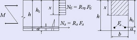
- it is recommended to use elements of such cross-sections that the relative height of the concrete compression zone calculated from the calculation ξ=x/h 0 did not exceed its limit value ξR, at which the limit state of the element occurs when the stresses in the stretched zone reach the design resistance R a. The boundary condition has the form
x ≤ ξ R h o or ξ ≤ ξ R (6.1)
Value ξR is determined by the formula:
o- characteristic of the compressed zone of concrete, determined for heavy concrete and concrete on porous aggregates according to the formula:
ξ o \u003d a - 0.008R pr; (6.3)
wherein R pr taken in MPa; coefficient A= 0.85 for heavy concrete and a = 0.8 for concrete on porous aggregates.
Voltage value σ A in reinforcement it is assumed at 0.002E A = 400 MPa equal for reinforcement of classes:
A-I, A-II, A-III, B-I and Bp-1: (R a - σ o);
A-IV, At-IV, A-V, At-V, At-VI, B-II, Bp-II and K-7: (R a + 400 - σ 0),
Ra- design resistance of reinforcement to tension, taking into account the coefficients of the conditions of operation of the reinforcement m a,o- the value of the prestressing of the reinforcement, taking into account losses at the tension accuracy factor m t< 1 .
If, when calculating bending elements, the coefficient of concrete working conditions is taken into account m b1 = 0.85, then 500 is substituted into formula (6.2) instead of 400.
We will perform further calculations for a beam with conventional (non-prestressed) reinforcement, while we will calculate the reinforcement section only for the lower part of the beam, in which tensile stresses act, this does not mean at all that in the upper part of the reinforcement beam (installed for technological reasons ) will not, but will greatly simplify the calculation.
When calculating elements of a rectangular section with a single non-prestressed reinforcement (when the design reinforcement is installed only in the tension area), you can use the auxiliary table 1 and the formulas:
M = A o bh² o R pr (6.4)
F a = M/ηh o R a (6.5)
A o \u003d x / h o (1 - x / 2h o) \u003d ξ (1 -0.5 ξ) (6.6)
η \u003d (1 - x / 2h o) \u003d 1 - 0.5ξ (6.7)
reinforcement ratio μ and the percentage of reinforcement μ 100 (%) is determined by the formulas:
μ = Fa/bh o, or μ = ξR pr /R a (6.8)
μ% = 100μ (6.9)
Based on the experience of designing cost-optimal reinforced concrete products, it is recommended to take:
μ% = 1÷2%, ;ξ = 0.3÷0.4 - for beams (6.10)
μ% = 0.3÷0.6%, ξ = 0.1÷0.15 - for floor slabs (6.11)
Table 1. Data for the calculation of bent elements of rectangular section, reinforced with single reinforcement (according to the "Manual for the design of concrete and reinforced concrete structures from heavy and light concrete without prestressing reinforcement (to SNiP 2.03.01-84)")

Stage 7. Calculation of the reinforcement section.
We can set the dimensions of the cross section of a reinforced concrete beam and the position of the reinforcement ourselves, based on technological requirements or other considerations. For example, we have decided that the beam will have a height h = 20 cm and a width b = 10 cm. Distance A the center of the cross section of the reinforcement from the bottom of the beam is usually taken within 2-3 cm. We will carry out further calculations at a = 2 cm. The design tensile strength for class A-III reinforcement according to
For an approximate calculation of the beam, it is convenient to use the calculator program. The Excel file with the calculator program can be downloaded if . Unfortunately, I could not find the name of the author of the program.
The calculation begins with the determination of the desired payload. For calculation prefabricated monolithic ceiling payload is:
- From the normative operational load of the floor with a safety factor (from SNiP). For example, for residential premises, the standard operating load is 150 kg / m2, the safety factor is 1.3, we get the operating load 150x1.3 \u003d 195 kg / m2.
- From the load from the weight of the blocks that fill the interbeam space. For example, aerated concrete blocks with a density of 500 kg / m3 (D = 500) with a thickness of 0.2 m. create a load of 500x0.2=100kg/m2.
- From the load from the weight of the reinforced screed. For example, a concrete screed with a thickness of 0.05 m. with a concrete density of 2100 kg/m3, it will create a load of 2100x0.05=105 kg/m2 (the weight of the reinforcing mesh is included in the concrete density index).
The total desired payload on the beam will be 195+100+105=400kg/m2 Next, specify the length of the overlapped span. For example, the span length is 4.6 m.
The step of the beams is the distance between the centers of the beams, determined by the dimensions of the block and the accepted width of the beam. For example, the length of the block is 0.61 m, the width of the beam is 0.12 m, the spacing of the beams is 0.61 + 0.12 = 0.73 m.
The width of the overlapped span, the cost of concrete and reinforcement are indicated in order for the calculator to calculate the quantity and cost of materials for overlapping. These indicators do not affect the calculation of reinforcement parameters.
In the "Beam parameters" section, the first two lines indicate the recommended beam dimensions. Taking into account the recommended dimensions, we select the dimensions of the beam based on design considerations. Since blocks with a thickness of 200 mm are used. and the thickness of the screed is 50 mm., then we take the height of the beam 0.25 m. If the screed will be poured with concrete not simultaneously with the beams, then the height of the beam should be taken without taking into account the screed.

We choose the number of bars of reinforcement from design considerations. The protective layer of concrete for reinforcement must be at least 20 mm, and the distance between the bars must exceed the size of the crushed stone fraction in concrete.
At the final stage, we analyze the results of the calculation and try to optimize the cost of the floor installation.
By selecting the number of reinforcement bars, we try to reduce the weight of the reinforcement per beam. By increasing the width of the beam, we try to avoid the use of transverse reinforcement, while the volume of concrete will increase by one beam.
For our example, we finally select two rebars in one row. Rebar diameter 12 mm. Cross reinforcement is not needed. The top reinforcement is also not needed, as the beam is poured with concrete in place.
This calculator program allows you to calculate the overlap with uniformly distributed load. It is not applicable if the ceiling, in addition to distributed, is also affected by a significant concentrated load from the weight of stone partitions, stoves, fireplaces, etc.
Next article:
This article is part of the project course Calculation of building structures from scratch which teaches the listener right choice design schemes, collection of loads, modeling and calculation building structures. The use of CAD within the framework of the course is deliberately minimized so that the student understands the algorithm of design actions and learns to design structural elements "manually". The course starts soon, be the first to know the news - join to our Community group!
Course program
- Reinforcement of a reinforced concrete beam. Calculation of reinforced concrete structures for the action of a bending moment
- Calculation of reinforced concrete structures by inclined sections
- Calculation of metal structures. Compressive Strength Test of Steel Column
- Fundamentals of reconstruction of buildings and structures. Reinforcement of the metal frame element
How does a reinforced concrete rectangular beam work? How to perform a strength test? Why do formulas in SNiP look like this?
Consider a simple (split, hinged) beam , to which a uniformly distributed load is applied :
Figure 1. Diagram of bending moments in a simple beam from a uniformly distributed load
This is a very common type of construction. For example, such calculation scheme may have longitudinal and transverse beams of precast concrete structures, spans of bridges, fragments monolithic floors etc.
Under the action of the load \(q\), bending moments arise in all unsecured sections of the beam. These moments are distributed along a parabola: from zero at the supports to a maximum in the middle. The maximum bending moment at the very center of the beam has a table value:
\[(M_(\max )) = \frac((q(l^2)))(8).\quad (1)\]
To ensure the strength of such a design, the calculator needs to check for the first group limit states to the action of the bending moment, in parallel reinforcing the stretched zone of the beam with working reinforcement. Following the instructions of the design standards (for example, SP 63.13330.2012 - an updated version of SNiP "Concrete and reinforced concrete structures"), the strength of the section of a reinforced concrete beam of rectangular section is ensured when the bending moment from the design load does not exceed bearing capacity beams:
\[(M_(\max )) \le (M_(ult)) = (R_b)bx\left(((h_0) - \frac(x)(2)) \right);\quad x = \frac( ((R_s)(A_s)))(((R_b)b)),\quad (2)\]
- \((R_b)\) - design compressive strength of concrete;
- \((R_s)\) - design tensile strength of reinforcement;
- \((A_s)\) - cross-sectional area of the working reinforcement.
The cross-sectional dimensions of the beam \(b\), \(h\), the working height of the beam \((h_0)\) and the height of the concrete compression zone \(x\) are shown in the following figure:

Figure 2. What happens in the beam in the limit state
Please note that in this example there is no reinforcement in the compressed zone of concrete. If the project assumes it there (Figure 3), then the strength test will take the following form:
\[(M_(\max )) \le (M_(ult)) = (R_b)bx\left(((h_0) - \frac(x)(2)) \right) + (R_(sc))( A"_s)\left(((h_0) - a") \right);\quad x = \frac(((R_s)(A_s) - (R_(sc))((A")_s)))( ((R_b)b)),\quad (3)\]
- \((R_(sc))\) - design resistance of reinforcement to compression;
- \(((A")_s)\) - cross-sectional area of reinforcing bars of the compressed zone.

Figure 3. Reinforced concrete beam with reinforcement in tension and compression zones in the limit state
In general, the work of a reinforced concrete beam under load in the limit state is an equilibrium state. The forces in the reinforcement and concrete are balanced, and this condition is used to determine the height of the concrete compression zone:
\[\sum ((F_x) = 0:) \quad (R_s)(A_s) - (R_(sc))((A")_s) - (R_b)bx = 0.\quad (4)\]
\[\sum (M = 0:) \quad (M_(\max )) - (R_b)bx\left(((h_0) - \frac(x)(2)) \right) - (R_(sc) )((A")_s)\left(((h_0) - a") \right) = 0.\quad (5)\]
Solving equation (4) with respect to \(x\) and replacing the sign "=" in equation (5) with the sign "≤ ", we come to the standard strength test, written in the design codes of reinforced concrete structures.
Is it possible to sum the moments about another point?
It is possible, but it would be more expedient to "get rid" of some component and simplify the calculations. As a rule, the working reinforcement of the tensile zone is chosen: since the point relative to which the moments are collected coincides with the center of gravity of the reinforcement, the arm of the resultant of this reinforcement is equal to zero.
Is it possible to change the signs of forces, moments?
Yes. The directions of forces and moments do not play a fundamental role. It is only important to adhere to the chosen sign rule within one calculation.
Unit control
At this point, almost all novice calculators “stumble”. Here are a few key rules to follow:
- beam length (span), load intensity, forces and bending moments - in the same units of measurement, for example: kN, cm, kN/cm, kNcm
- all geometric characteristics of the section - in the same units of measurement, for example: cm, cm 2
- design resistances must be consistent with the units of measurement of forces and geometric characteristics. If [kN] and [cm] are selected, then the design resistances should be converted from [MPa] to [kN/cm2], for example: 450 MPa = 45.0 kN/cm2
One of the few places where design resistances can be left in MPa is the formula for determining the height of the compressed concrete zone. In other cases, these characteristics should be reduced to the correct units of measurement.
How to find the center of gravity of reinforcement?
The definition of the center of gravity is discussed in the following video.
Work of a tee reinforced concrete beam
If symmetrical overhangs appear at the edge of the beam on both sides of the section (like a slab), the beam becomes a T-beam. The operation of such a structure in the limit state can develop according to two scenarios:
- the neutral axis passes in the shelf, and only its upper part is compressed (Figure 4)
- the neutral axis passes in the rib of the beam, and the compression is experienced by the entire flange and the upper part of the rib (Figure 5)
To understand which script to use, you should check:
\[(R_s)(A_s) \le (R_b) \cdot ((b")_f) \cdot ((h")_f) + (R_(sc))((A")_s).\quad (5 )\]
If the condition is met, then the boundary of the compressed zone is located in the flange, otherwise - in the edge of the beam.
Boundary of the compressed zone - in the shelf
If only part of the tee flange is compressed, the bending moment strength test becomes:
\[(M_(\max )) \le (M_(ult)) = (R_b) \cdot ((b")_f) \cdot x\left(((h_0) - \frac(x)(2)) \right) + (R_(sc))((A")_s)\left(((h_0) - a") \right).\quad (6)\]
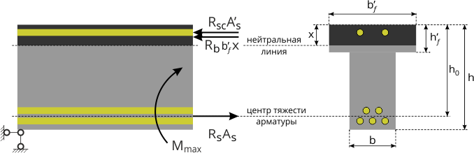
Figure 4. The work of the T-beam of the reinforced concrete structure, if the boundary of the compressed zone passes in the flange
As you can see, this is the old strength test, only instead of the width of the rectangular section, the width of the tee shelf is now used.
The boundary of the compressed zone is in the rib
This scenario is included if condition (5) is not met. In this case, the bending moment strength test takes the form:
\[(M_(\max )) \le (M_(ult)) = (R_b)bx\left(((h_0) - \frac(x)(2)) \right) + (R_b)\left(( ((b")_f) - b) \right)((h")_f)\left(((h_0) - \frac((((h")_f)))(2)) \right) + ( R_(sc))((A")_s)\left(((h_0) - a") \right).\quad (7)\]

Figure 5. The work of the T-beam of the reinforced concrete structure, if the boundary of the compressed zone passes in the rib
Following this scenario, the height of the compressed concrete zone must be determined by the following formula:
\
Notice the two separate rectangles shown in Figure 5 (right). They illustrate the actual breakdown of the section into elements to determine the bearing capacity. The first element is the edge of the beam, conditionally extended to the top of the flange, i.e., in fact, the usual rectangular section. The second element is the overhangs of the compressed shelf, conditionally combined together (since they are located symmetrically and work together). It is this geometry that corresponds to formula (7), introduced into the design standards for reinforced concrete structures.
Next time we will learn count reinforced concrete structures to the action of transverse forces. Good luck!
Information sources
- Code of rules SP 63.13330.2012. Concrete and reinforced concrete structures. Basic provisions. Updated edition of SNiP 52-01-2003 / NIIZhB im. A. A. Gvozdeva. - M.: 2011. - 156 p.
- Design and calculation of reinforced concrete and stone structures: Proc. for building. specialist. universities / N. N. Popov, A. V. Zabegaev. - M.: Higher. school, 1989. - 400 p.
- Eurocode 3: Design of steel structures. Part 1-1: General rules and rules for buildings / EN 1993-1-1:2005 i rules for disputes / - K .: Minregionbud of Ukraine, 2011. - 150 p.)
- Code of rules SP 16.13330.2011. Steel structures. Updated edition of SNiP II-23-81* / TsNIISK im. V. A. Kucherenko. - M.: Ministry of Regional Development, 2011. - 173 p.
- EN 1990 Eurocode - Basis of structural design (Eurocode: Fundamentals of structural design. Nastanova / National Standard of Ukraine DSTU-N B V.1.2-13:2008 (EN 1990:2002, IDN) / - K .: Minregionbud of Ukraine, 2009. - 204 p.)
- SNiP 2.05.03-84*. Bridges and pipes / - M .: CITP Gosstroy of the USSR, 1985. - 200 p.
- Code of rules SP 20.13330.2011. Loads and impacts. Updated edition of SNiP 2.01.07-85* / TsNIISK im. V. A. Kucherenko. - M.: Ministry of Regional Development, 2011. - 96 p.