18-01-2013: Vladimir
in diagram 1 in the formulas for the moment on supports l is not squared?
18-01-2013: Doctor Lom
With a concentrated load, the moment formulas cannot include the length squared.
27-02-2013: Vadim
27-02-2013: Doctor Lom
To calculate continuous beams with three spans or more, it is easier to create a three-moment equation. I can’t explain what this equation is in commentary format, and I don’t have an article on this topic yet. You can see the article: “Double-span beams”. The principles outlined in this article can also be applied to three-span beams.
11-05-2013: Dmitriy
"Table 2. Single-span beam with rigid pinching on support A and hinged support B. Figure 1.2" Is it possible to calculate using this scheme for x=a?
I need to know how the shaft will bend at the point of contact of the cutter.
11-05-2013: Doctor Lom
Can. However, in your case, it would be more correct to calculate not only the bending moment, but also the torque.
11-05-2013: Dmitriy
Can you post the formula for my case when x=a. I am afraid that the calculation error will exceed the technological one from recalculating such a long formula.
- The book says that shafts bend very little due to rotational moment, so they are not usually taken into account.
11-05-2013: Dmitriy
"Table 2. Single-span beam with rigid pinching on support A and hinged support B. Figure 1.2" Can you post the formula for the special case x=a? This means that x=a was accepted during integration. Then the formula should be significantly simplified.
Thank you!
11-05-2013: Doctor Lom
x=a is a special case of the above formulas, i.e. at a distance from the beginning of the beam equal to a:
Ma = Aa + MA. It's the same story with deflection.
Moreover, if we consider a section of the beam at x>a, then the formulas will be even more complicated. There is nothing I can do about it, but I can advise the following. The maximum deflection in your case will be when the load is applied approximately in the middle of the shaft, i.e. when a?b, the closer you move the cutter to one or the second support, increasing the distance a or b, the less the deflection will ultimately be. Therefore, it is much easier to calculate the maximum deflection according to scheme 1.1, and to be sure, make an additional margin, i.e. increase the deflection calculated in this way by 3-5%; it is unlikely that the deflection obtained by accurate calculation will be greater, but it can be increased by 10-15% for greater confidence.
14-05-2013: Faith
Hello, is it possible to see somewhere the calculation (derivation of the formula for the bending moment) for the load case in Table 1, paragraph 2.5 for a triangle?
14-05-2013: Doctor Lom
All the formulas used to compile the tables remained on paper (typing them took too long). In addition, there are several methods for calculating statically indeterminate structures. In this case, we used a technique described in sufficient detail in the article “Two-span beams” (http://site/item230.html)
27-07-2013: Dmitriy
By Dear Doctor Lom! How to correctly calculate a three-span beam on hinged supports against a uniform load if all spans are different?
02/27/2013: Doctor Lom
To calculate continuous beams with three spans or more, it is easier to create a three-moment equation. I can’t explain what this equation is in commentary format, and I don’t have an article on this topic yet. You can see the article: “Double-span beams”. The principles outlined in this article can also be applied to three-span beams.
This calculation has a very specific practical application - calculation of loads on truck axles. The truck has a trailer with 4 legs. The first one rests on the tractor's coupling device, the other three - the axles of the wheels located at a distance (base) from the coupling and at the same distance from each other. Evenly/unevenly distributed load I managed to create a point load with a certain coordinate inside the body. But the distribution of the load between the wheel axles is alas. They will be grateful for any help/pointers to the material.
27-07-2013: orderly Petrovich
Eh, my friend, you need to go to another hospital, we don’t even have such a department.
27-07-2013: Doctor Lom
Petrovich is right, the calculation of rotating shafts and mechanisms is a separate story. In addition, it should be taken into account that the loads will not be static, but dynamic and shock, and not only vertical, which are most often considered in construction, but also horizontal, which arise when moving with acceleration.
But you can look at the articles "Multi-span continuous beams". In particular, they discuss the calculation of three-span beams. True, your specific case is not considered, but the designer’s skill lies in finding a way out of complex situations by simplifying them. For example, in your case, when calculating vertical loads (from the weight of cargo), it is not at all necessary to consider the tractor’s coupling device as a support. I’m certainly not an expert in the automotive industry, but it seems to me that most coupling devices are designed to absorb horizontal loads that arise during accelerated movement, while up and down movement is quite possible, but I could be wrong.
This way you will get a two-span beam with two consoles. And although I don’t have such a calculation scheme, here you can use the principle of superposition for a uniformly distributed load, i.e. You can separately calculate a two-span non-cantilever beam and two consoles, and then add the resulting values of the required parameters. And if the calculation is carried out for a concentrated load inside the spans, then the consoles do not matter at all.
But still, don’t forget Petrovich’s advice; calculating rotating shafts is not for me.
29-07-2013: Dmitriy
orderly Petrovich - interested in determining the load on the axles in a static state. In this mode, the reaction of the axles, the gravity of the load and the gravity of the trailer itself fully corresponds to the scheme with the beam and the reactions of the supports.
29-07-2013: orderly Petrovich
Of course, it’s not my business to meddle in doctor’s affairs, but while they’re resting, I’ll have a chat with you.
If for a static state, then your calculation and the bottle you drink is not worth it, because you only need to calculate two axes. After all, what is the third axis needed for? - for insurance. If a two-ton passenger car's tire bursts or flies off, that's one thing, but if a trailer has 40 tons of weight, and at high speed, then you won't have much fun. Therefore, slowly calculate for yourself all the options for a single-span, double-cantilever beam, and there will be only two of them, and two more for a single-span, single-cantilever beam, if you consider the coupling device as a support, and choose the most loaded one.
This is how I think about this matter.
30-07-2013: Dmitriy
Petrovich, at the weight control they are punished for overloading on any of the specific axles. Since there are three of them at the back, the load (in an unknown way) is still divided among all three axles.
I can do the math - I can arrange pallets with cargo in such a way that all axes will not be overloaded.
30-07-2013: Dmitriy
After all, what is the third axis needed for? - Here http://www.packer3d.ru/online/veh-by-pal it is clearly shown that all axes are involved
30-07-2013: orderly Petrovich
Wow! So I would have said right away, we need to pull everything out of you with tweezers. I drew a picture for myself for a friend, but oh well.
As I understand it, the kakulator is designed for evenly spaced pallets, giving an evenly distributed load. You, my dear, are planning to arrange the pallets in such a way that the load on the axles is evenly distributed.
I’ll tell you right away: don’t give a damn about this matter. Theoretically, this is possible, but for that half of the load, or more, needs to be thrown away.
In addition, I wonder if there are scales that determine the load on each axle, rather separate scales for the tractor and the trailer. That's how it is, no?
If so, then the recipe is simple, from the beginning of the trailer to the first rear axle, the height of the pallets is 2/3 of the total height, from 1 rear to 3 rear axles, gradually increase the height of the pallets to the full height, then to the full height, if the trailer is such as in cakulator.
And you will have a more even distribution of the load between the axles. Or rather, you don’t even need to count - the size of the pallets won’t allow it. In addition, too much data will be required for calculation.
And if old Petrovich made a mistake with the height, then the scales will tell you whether you need more than 2/3 or less.
Oh, someone’s throat is dry from all this talk, I should go get a beer while the doctor is away.
25-11-2013: Anton
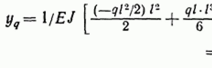
Good afternoon. I have a question about formula 1.2 in table 2. When calculating the deflection using this formula and substituting the condition x=a=b=l/2 into the resulting expression, the expression given in the formula above does not work. The difference lies in the difference in the number in front of the product E.I. When substituting, the result is not 107, but 109. Tell me, what is the error? Can this calculation method be an approximate one?
25-11-2013: Doctor Lom
The fact is that, using the formula, you determine the value of the deflection in the middle of the span and at the bottom of the resulting expression it will actually be 109.7. Meanwhile, a beam with rigid clamping on one support and hinged on the second support, the maximum deflection will be shifted towards the hinged support. Line 1 of Table 2 shows exactly this maximum value. Since the distance from support A to the cross section with the maximum span is greater than 0.5l, then to determine this value you should use formulas that take into account the action of the transverse force at the point of application (or determine the deflection value by counting from support B, taking into account the angle of rotation at support B ). It’s not that these formulas are so complicated, but they take up a lot of space, and therefore are not given in the table.
26-11-2013: Anton
Thank you for your answer. Yes, indeed, you are right. The point of maximum deflection will be located a little closer to the middle of the beam to the hinge support. But here I have another question. Having differentiated the expression for finding the deflection, having found the extremum of the function, I thereby obtained x of the maximum deflection. Substituting this value of x into the deflection formula under the same conditions a = b = L/2, I received 107.555 in the denominator. I don’t know what the problem is, but I found the same formula for a special case in other sources (a=b=L/2). I’m interested in this because I do calculations at work and need to get an accurate result.
26-11-2013: Doctor Lom
But here, when we are talking about tenths of a percent and in general about fractional numbers obtained as a result of rather complex calculations, the tabular values should really be considered as approximate. The value you obtained is more accurate; the table value gives a larger deflection, and therefore contributes to a small additional margin (0.2%) when calculating for group 2 of limit states.
27-11-2013: Anton
You cleared my doubts. Thank you very much for the explanation and quick answers!
06-12-2013: Maksim
2 table, diagram 3.1. At point B, the value of the moment on the diagram is not equal to the value of the applied moment at this point?
07-12-2013: Doctor Lom
Does not work, more precisely the meaning moment on the diagram at point B is equal to the value of the moment applied at point B. With this direction of action, the moment is considered negative (-M), respectively, when a negative bending moment acts on support B, a positive bending moment occurs on support A, but the support reaction on the support And it will be negative. If you substitute all the values given in the table into the moment equation, then at x = l, on support B you will get the same negative moment Mb = -M.
07-12-2013: Maksim
for example, m=10, L=2.
then Ax = 3*10/2*2 = 7.5
Ma = 10/2=5
Mb= 5+ 7.5 = 12.5
07-12-2013: Doctor Lom
You do not quite correctly understand the essence of the formulas and do not follow the signs:
not Ax = 3*10/2*2 = 7.5 but simply the support reaction A = 7.5. x is a variable indicating the distance from the beginning of the beam to the cross section in question. At point B the value is x = L = 2.
Further, if m = 10, then Ma = -5. Then on support B
Mb= -5 + 7.5x2 = 10
09-07-2014: Zarif
Dear Doctor.
Do you have the magnitude of the diagram M for pitched roofs?
09-07-2014: Doctor Lom
Look at the article "Examples of calculation of rafters and sheathing" there are diagrams corresponding to the calculation.
11-02-2015: Sanmart
Dear Doctor Lom!
Do you have any formulas for calculating the maximum deflection and moment for a two-span beam fully loaded with a uniformly distributed load with spans of different lengths?
The scheme is almost like 2.3, but q is distributed from A to C.
If you are too lazy to enter these formulas into the editor, send them somehow, like in a scanned format, and I will return them to you in the editor.
11-02-2015: Doctor Lom
The fact is that it is physically impossible to present all possible loading cases for all possible options. So you're out of luck - you'll have to use general formulas. At your service is the section "Statically indeterminate structures" and in particular the articles "Double-span beams" and "Statically indeterminate beams. Equations of three moments." Here I will say that you can determine the maximum moment on support B by using the same diagram 2.3 twice, namely
MV = M1 + M2 = - q(l1^3 +l2^3)/(8(l1 + l2)).
To determine the deflections of cross sections relative to the x-axis, you must first determine the angles of rotation on the supports, and then use the general differential equation deflection. More details in the article "Basics of strength strength materials. Determination of beam deflection." But in any case, whatever the length of the second span, the maximum deflection in one of the spans will be greater than ql^4/185EI and less than 7ql^4/768EI. If such limits are too vague for you and greater accuracy is required, then only calculation.
12-02-2015: Valentine
Hello Doctor Lom. I wanted to clarify with you the special case described in section “Table 3. Two-span beam with hinged supports. Fig. 1.3.” Is it possible for you to supplement it based on the fact that in this case the distances l are not equal, but different, i.e. l1 and l2. Interested in reactions in supports and moment in support. Very urgent request. Thank you.
12-02-2015: Sanmart
Eh... I will remember the long-forgotten strength of materials...
Nevertheless thank you!
12-02-2015: Doctor Lom
I literally answered a similar question yesterday. The tables provide formulas for special cases, however, the most common ones. For general cases like yours, the formulas become too cumbersome and clarity is lost. In such cases, it is necessary to perform a full calculation using the moment method or the force method, since you only have one unknown support reaction.
Nevertheless, the tables given are very convenient for preliminary assessment of structures. For example, if your load case is like the one shown in Table 3, design scheme 1.3, then when the length of one of the spans decreases, the calculated values and ground reactions and the moment at the support and other quantities will definitely be less. Thus, a simplified calculation will only increase the safety margin; this knowledge is quite sufficient when calculating a structure manufactured in 1-2 copies. Well, for mass-produced structures, accurate calculations are required.
21-03-2015: David
Dear Doctor Lom
I have gable roof with identical sides with a ridge without support, but rigidly fixed rafters (welding), the bottom can be considered as a hinge. Is it possible to use the formula Table 2 2.1 or something else to calculate deflections, if you don’t mind, write a formula or link
22-03-2015: Doctor Lom
This will not be entirely correct, and weld must be designed for appropriate loads to ensure rigidity. Perhaps your design would be more correctly considered as a triangular arch with a tie on supports (see the corresponding article).
02-04-2015: Vladimir
Table 1, diagram 1.1 The formula for deflection, in my opinion, is incorrect. Logically, it should be f(l) = 0. But in the proposed formula this does not happen.
02-04-2015: Doctor Lom
The given formula for determining the deflection, as well as the formula for determining the moment, is valid for the section from 0 to l/2 (the middle of the span where a concentrated force is applied). Since the beam (method of support) and the load are symmetrical, I did not consider it necessary to provide a formula for determining the moment and deflection in the second section from l/2 to l, as there are enough difficulties.
But if you really need it, then in this section (from l/2 to l) you should additionally subtract Q(x - l/2)^3/6 from the indicated expression.
03-04-2015: Vladimir
Thanks a lot. I didn't see that 0 03-04-2015: Doctor Lom
14-08-2015: Martin
The question is off topic, but I have no idea where exactly to write... 14-08-2015: Doctor Lom
I’m actually not an expert in MRI equipment, but there seems to be nothing wrong with a metal frame (there won’t be a metal frame, there will be reinforcement in reinforced concrete structures or something else). Look for the standards for the equipment of MRI rooms, there also seem to be no restrictions on the design of walls and ceilings. 09-09-2015: Yuriy
Dear Doctor Lom 09-09-2015: Yuriy
I can’t solve problems with calculating 3 and 4 door awnings. Please help 09-09-2015: Doctor Lom
A similar situation is discussed in the article “Determination of pull-out force (why the dowel does not stay in the wall).” The only difference is that you will have two canopies on top. To simplify the calculations, we can assume that the distance between the upper canopies is significantly less than the distance between the upper and lower canopies, then we can assume that the forces acting on the upper canopies are the same and in total equal to the lower force. But in any case, the load on the upper canopy will be greater than on the middle one. When the middle canopy is shifted to the middle of the door height, its role in terms of the perception of the pulling force will be significantly reduced, but at the same time the stability of the door will increase. 10-09-2015: Yuriy
You know 10-09-2015: Yuriy
for two loops it turns out that the forces are equal only with the opposite sign 10-09-2015: Doctor Lom
Your mistake in choosing a calculation scheme. With 3 canopies, you consider the door as a two-span beam with relatively low stiffness, in other words, as a flexible beam that will have some deformation under the influence of support reactions. Meanwhile, in the plane of action of the moment, the height of the beam is the width of the door 1 m, which is significantly greater than the span between the 2 upper canopies. Those. the door can be conditionally considered as an absolutely rigid beam, to which the calculation schemes given in this article are not applicable. The door in this case can be considered as a kind of cross section. 15-10-2015: Sergey
Good afternoon Doctor Lom. Excuse my ignorance. Please tell me what E means in the formula for calculating the deflection of a beam and how to determine it (E) 15-10-2015: Doctor Lom
E is the modulus of elasticity of the material you are going to use for the beam. The values of elastic moduli for various building materials can be found in the article “Calculated resistances and elastic moduli for various building materials.” And the physical meaning is in the article “Elastic and strength characteristics of materials.” 13-03-2016: Vyacheslav
Good afternoon. 13-03-2016: Doctor Lom
That's right, of course Mx=Ax-qx^2/2. I'll try to fix it now. Thank you for your attention. 30-03-2016: Timur
Hello! 30-03-2016: Doctor Lom
Under the action of a uniformly distributed load, the bearing capacity of a rigidly clamped beam is 1.5 times greater than the same beam, but on hinged supports. This does not depend in any way on the length (if we compare a simply supported and rigidly clamped beam of the same length), but the type of acting load can influence the value of the difference. And such a difference in load-bearing capacity arises due to the fact that the maximum moment for a simply supported beam will be closer to the middle of the span, and for a rigidly clamped beam - on one of the supports (or on both supports, if the load is symmetrical). 31-03-2016: Timur
I just thought that the load-bearing capacity would increase by 5 times rather than 2. This is essentially tensile steel. You can walk on a wire of a couple of millimeters. Or will sagging happen over time? 31-03-2016: Doctor Lom
This article provides calculation schemes for relatively rigid beams. As a rule, the height h of such beams is 1/10 - 1/20 of the span length l. And the deflection of such beams, as a rule, does not exceed f? h/4 - h/2. Steel wires, ropes and other flexible (I would even say absolutely flexible) threads are calculated using completely different formulas and the diagrams will have a different appearance. As a rule, the deflection f of flexible threads is at least 5h - 6h. In flexible threads, the stresses caused by the action of the bending moment are extremely insignificant compared to the tensile stresses that arise during such a significant deformation. These tensile stresses must be compensated by horizontal support reactions. However, the calculation of flexible threads is a separate topic. 15-04-2016: Stanislav
Hello! Question on table 1. “Single-span beam with rigid pinching on supports” according to paragraph 1.3. Moment on supports Ma and Mb. Please tell me, is there an extra two in the equation? 15-04-2016: Doctor Lom
No, not too much. And it's quite easy to check. If a = l/2, i.e. both forces are applied at one point in the middle of the beam, then the equation of moments will be reduced to Ma = Mv = -2Ql/8 = -Ql/4. We get the same result by adding up the values of the moments when using calculation scheme 1.1. 15-04-2016: Stanislav
I'm sorry. The question I asked earlier is not correct. Using your tables (for hinged supports and for rigidly fixed ones), I calculated the maximum deflections in the case of the action of two concentrated forces with the same distance from the supports (Table 1 - paragraph 1.3). As a result, it turned out that the deflection in the case of hinged supports is less, than deflection in the case of rigidly fixed ones. Although logically it should be the other way around. Please clarify. Is there a possibility that you have an error in the design diagram for rigid supports 1.3? 15-04-2016: Doctor Lom
I don't know how you did it. I assume that you substituted the moment value into the deflection formula without taking into account the “-” sign. Again, if a = l/2, i.e. both forces are applied at one point in the middle of the beam, then the maximum deflection will be f = -Ql^3/96EI. We get the same result by adding up the deflection values using calculation scheme 1.1. 16-04-2016: Emin
Where can I find a design diagram for a single-span beam with a rotary hinge in the middle? 16-04-2016: Doctor Lom
What do you mean by a swivel joint in the middle? If this is a support that prevents the beam from moving vertically, but does not prevent the change in the angles of inclination of the cross sections of the beam, then such a support should be considered as an intermediate support of a two-span beam, Table 3. If this hinged support is located in a perpendicular plane, then its presence only affects the determination the flexibility of the rod in a given plane and when calculating vertical loads is not taken into account. 16-12-2016: Michael
Hello! Tell me how to determine horizontal (pulling out) reactions in a beam design with two embedments? 16-12-2016: Doctor Lom
In general, beams are considered to be fairly rigid rods (restrictions on the maximum permissible deflection contribute to this) and therefore, to simplify calculations, the horizontal support reactions resulting from deformation are assumed to be zero. But in general, if there is such a need, then first the deflection is determined and a diagram is drawn. Then the change in the length of the neutral axis of the beam is determined - the procedure itself is quite complex, and then, depending on the elastic modulus of the beam material, the forces required for such a change in the length of the beam are determined. 17-02-2017: student
Doc, sorry for the stupid questions. I mastered the construction of diagrams in Excel, for a beam pinching-hinge, bending moment in the span M(x) (Table 2 p. 2.1). The result is that at the end of the beam the function is not equal to 0. Fig https://yadi.sk/i/Cal1RKes3EDm6W 17-02-2017: student
Doc, for a purely theoretical understanding: is it possible to not install or reduce reinforcement in places where there is zero bending moment in the span of a beam? Or are the shear forces comparable at these points? 17-02-2017: Doctor Lom
I’ve already said that I’m not familiar with Excel, so I’m unlikely to be able to point out where your error crept in. But in general, if we substitute the values at x = l into the moment equation given for this design scheme, then the moment at support B is equal to zero: 22-08-2017: Ivan
Good afternoon For a scheme with sliding terminations at the ends of the beam, is it permissible to use the deflection calculation formula for option 1.1 (two rigid terminations at the ends)? As I understand from the comments, the horizontal support reactions are assumed to be zero; accordingly, the rigid embedment in this case is the sliding one. Do I understand correctly? 23-08-2017: Doctor Lom
Yes, it is permissible if the beam has the appropriate rigidity. In general, horizontal support reactions always arise due to the distribution of internal stresses; it’s just that the greater the rigidity of the beam, the less their influence on the overall work of the rod. Therefore, as a rule, when calculating rigid beams, the influence of possible horizontal support reactions in the safety factor is neglected, taking them equal to zero. Well, for flexible threads, the default sliding seal is not suitable as a support. As is already known, a beam is statically determinate if it is supported on two hinged supports (one movable and one fixed) or fixed at one end, i.e. if three external connections are superimposed on it. An exception is multi-span hinged beams (consisting of several individual beams connected to each other by intermediate hinges), which can be statically determinable even if the number of external connections is more than three (see this in § 3.7). In Fig. 85.7, a, b shows two statically indeterminate beams; four external constraints are imposed on each of them, and, consequently, these beams are statically indeterminate once. In Fig. 85.7, c shows a beam with six external braces; it is three times statically indeterminate. The degree of static indetermination of a beam (which does not have intermediate hinges) is equal to the excess (extra) number of external connections (over three). Statically indeterminate beams are often called continuous beams. The calculation of continuous beams, like the calculation of any statically indeterminate systems, cannot be performed using equilibrium equations alone; It is always necessary to create additional equations (displacement equations) that take into account the nature of the deformation of the beam. In Fig. 86.7, and a statically indeterminate beam is depicted once. To calculate this beam, it can be represented as a statically determinate beam shown in Fig. 86.7, b, obtained from the right support given as a result of discarding. A statically definable system obtained from a given one by removing redundant connections is called a basic system. The beam shown in Fig. 86.7, b, is the main system for a given beam (Fig. 86.7, a). In addition to the given load q, the main system (Fig. 86.7, b) is affected by the unknown reaction RB of the discarded connection. Under the action of load q the beam shown in Fig. 86.7, b, is deformed and its free end moves down (Fig. 86.7, c) by an amount that can easily be determined by the method of initial parameters: Under the action of force RB, the free end of the beam shown in Fig. 86.7, b, moves upward by an amount (Fig. 86.7, d), which can also be determined by the method of initial parameters: Under the simultaneous action of a given load q and force, the deflection of the free end of the beam shown in Fig. 86.7, b, is determined by the expression This deflection is zero, since the deflection of the right end of a given beam (Fig. 86.7, a) is zero: Consequently, the actual reaction occurring at the right support of a statically indeterminate given beam is equal to. The bending moment M and the shear force Q in the section of a given beam can now be determined using formulas (2.7) and (3.7), as in the statically determinate beam shown in Fig. 86.7, a: The diagrams Q and M constructed using these expressions for a given beam are shown in Fig. 86.7, f, g. The calculation of a given beam can also be performed using other basic systems, for example, those shown in Fig. 86.6, h, i. Continuous beams are usually calculated using the so-called three-moment equations. This method of calculation allows one to avoid drawing up additional equations like (81.7). In addition, this method allows us to obtain additional equations with the number of unknowns in each of them no more than three, which, given a high degree of static indetermination of a given beam, simplifies the solution of the system of equations. Let us now consider the calculation of continuous beams using three-moment equations. In Fig. 87.7, and shows a section separated from a multi-span continuous beam under the influence of some load. Beam supports are designated from left to right by numbers, etc. The span lengths of a continuous beam are indicated (also from left to right), etc. The index for the length of each span I corresponds to the number of the right support of this span. The moments of inertia J of the cross sections of the beam are constant along the length of each span; in different spans the moments of inertia can have different values. We obtain the basic system for calculating a continuous beam by removing from it the connections that prevent the mutual rotation of adjacent sections of the beam above its supports, that is, by placing hinges above the supports of the beam (Fig.). Unknown are the bending (support) moments, etc., arising in the sections of a continuous beam above the supports. We consider unknown moments to be positive when they cause tension in the lower fibers of the beam. Consider two beam spans adjacent to the support, shown in Fig. 87.7, v. Here the dotted line shows the curved axis of the beam. In Fig. 87.7, d shows sections of the beam directly adjacent to the support. Here is the angle of rotation of the cross section belonging to the left span and directly adjacent to the support, and is the angle of rotation of the section belonging to the right span and also directly adjacent to the support. Both of these sections, in essence, represent one cross section located above the support, and therefore their angles of rotation are the same, i.e. The rotation angles and can be considered as a consequence of the impact on individual single-span beams shown in Fig. 87.7, d, given loads, as well as unknown support moments. Condition (82.7), therefore, means that the angle of rotation of the right end of the left of the beams shown in Fig. 87.7, d, is equal to the angle of rotation of the left end of the right beam, i.e., the mutual angle of rotation of these ends is zero. Unknown moments, etc. have such values that the specified condition is satisfied not only for support , but also for all intermediate supports of a continuous beam. Let's find the values of the angles using the graphic-analytical method. In Fig. 87.7, f, g show fictitious beams for spans loaded with a fictitious load. In Fig. 87.7, e shows a fictitious load corresponding to the action on these spans of the load specified on the beam, and in Fig. - the influence of unknown moments on them Based on the second of formulas (80.7), the angles and are respectively equal to the fictitious transverse forces and those arising on the supports of the spans of fictitious beams, i.e. where (Fig. 87.7, f), as well as and (Fig. 87.7, g) are the reactions of the supports of fictitious beams. Let's look at real examples of support nodes or connections of structures and determine what we are dealing with: a hinge or pinching. This is a classic hinge case. The depth of support of the slab is dictated by the standard series, and it is less than the height of the slab section. In such conditions, bending, the slab will calmly turn on a support - on a hinged support. Moreover, it is impossible to pinch the slab by inserting it deeper into the wall, because moments on the support will immediately appear in it (with a hinged design, the moment on the support is zero), and there is practically no upper reinforcement to absorb these moments in prefabricated slabs. Calculation diagram for such a slab: It all depends on the depth of insertion of the slab into the wall. If, with a slab height of 200 mm, you support the slab by 150-200 mm, then this is a hinge. If the upper reinforcement extends onto the support to the length of the anchorage or special measures have been taken in the form of welding plates (washers) at the ends of the reinforcement, then this is pinching. If the depth of support is “neither this nor that” - i.e. greater than the section height, but less than the anchorage length, then this is an unpleasant case when you need to not only design, but also calculate all the details of the assembly and check whether they can withstand such abuse. Firstly, the installation of upper working fittings is already mandatory. Secondly, it must be designed for the moments that arise during this pinching. Thirdly, the sufficiency of its anchoring must be checked by calculation. The design scheme for a single-span slab is as follows: For a monolithic beam, everything is similar; the embedment depth for the pinched version can only be saved by bending the top rod down. But for both the slab and the beam, the load of masonry must be sufficient and verified by calculation. This is a standard scheme with a support in the form of a pinching - there should be no hinge here in any case, there shouldn’t even be partial pinching - only a 100% rigid knot. Otherwise, the system will be geometrically variable: the balcony under load will rotate on the support with all the consequences. Therefore, when designing the support of a cantilever balcony, you need to very carefully develop and calculate the rigid support unit. In the standard series 2.130-1 issue. 9 you can familiarize yourself with the support units of balcony slabs and understand by what principle pinching is achieved. Firstly, this is a sufficient insertion of the slab into the wall. Secondly, this is a significant load from the masonry of the wall on top. Thirdly, this is mandatory anchoring top parts of the slab in a compressed structure - in the solutions of the series this is done by welding anchors to the mortgage in the balcony slab, which are securely fastened in the wall structures (the fastening is calculated). All three conditions must be balanced and together give reliable pinch. When supporting beams, you need to use the same principle: the depth of support plus the anchorage of the top of the beam. In the case of a monolithic cantilever slab or beam resting on a monolithic wall, it is necessary to insert the upper reinforcement of the console into the wall to the length of the anchorage - this will ensure pinching. If the balcony turns into a slab (i.e., in fact, it is a slab with a cantilevered balcony overhang), then there is no need to worry about a rigid assembly here - just a simple hinged support on the wall is enough. If you are making a balcony in an existing building, it is very difficult to design and execute a clean bracing, so try to avoid pure cantilevers and make balconies with bracing. This solution is chosen in several cases: if it is dictated by an architectural solution; if the construction is carried out in an existing building; if the console without a strut cannot withstand a significant load. What's good about this console? The fact that the structure as a whole is a cantilever, but individually each support node is hinged with limited movement vertically and horizontally - and such nodes do not require calculations, and they are much easier to design and implement than pinching. The main thing here is to ensure reliable limitation of horizontal movement: if the strut is fastened with bolts, then there should be enough of them to pull out; if the structure is simply laid into the wall, then there must be anchors inserted into the masonry, etc. The design diagram of such a balcony is as follows: A horizontal beam is fixed in the wall with limited movement vertically and horizontally. It is uncut in length. In the span (or at the edge), the horizontal beam is hinged on the strut, which in turn rests on the wall with limited vertical and horizontal movements. Such a beam in the middle spans always has a hinged support, but on the outer supports there can be both pinching and a hinge. Everything is determined by the size of the spans and the possibility of pinching the beam. If the spans are large, or if the dimensions of the spans are different and adversely affect the span moment in the outer spans (for example, the outer spans are much larger than the middle ones), then you can try to use pinching on the outer supports. Basically, the outer supports are made hinged. This slab has exactly the same principle as the multi-span beam described in the previous case. The outer supports of such a slab can be beams, or they can also be the walls of the building. If the outer supports are beams, then pinching when leaning on them is difficult to organize; hinged support is standardly used here. I would like to draw your attention to the following point. With a large multi-span ceiling, it is necessary to make an expansion joint in it. If the loads are significant, then when hinged on the outer supports in the outer spans, significant bending moments arise, requiring significant reinforcement - and this is not always rational for slabs of small thickness. In this case, I recommend considering the option of installing a seam not on the beam, but in the span: then the two slabs will have a cantilever overhang. In this case, the moments will be balanced and the reinforcement will be harmonious. The basement wall is always affected by horizontal soil pressure, and the deeper the basement, the greater the influence of horizontal pressure on the structure. When determining the design scheme for a basement wall, you need to consider the scheme in two directions. The first and most important thing is a vertical section along the wall. There are two nodes to consider: upper and lower. There may be a lack of support in the upper node (if the ceiling does not rest on the wall); a hinge with limited horizontal movement (if there is a hinged support for the floor - for example, prefabricated slabs); rigid node (if the connection between the basement wall and the ceiling is rigid - for example, a monolithic structure). In this case, support is meant in the horizontal direction, because Our main load is horizontal soil pressure. In the lower junction of the wall with the foundation strip it is mostly found to be rigid - organizing a hinge there is labor-intensive and does not make much sense. Now about another, horizontal section of the wall. If the length of the wall is not limited in any way in its movements (there are no perpendicular walls), then there is no need to consider the horizontal section in the calculation. But if there are perpendicular walls located quite often, then you also need to count the wall in the horizontal direction, because On one side, soil pressure acts, on the other side, the walls serve as supports, and a multi-span continuous structure is obtained, in which both span and support moments arise - accordingly, it is necessary to check the horizontal reinforcement of the wall, taking into account the location of perpendicular walls. Such a wall is considered to be a multi-span continuous slab 1 m wide (a meter-long horizontal strip is conventionally cut out of the wall); the middle supports are hinges, and the extreme ones depend on the connection with the perpendicular walls - basically, this is pinching. Basically, in reinforced concrete, the coupling scheme is pinching, because the hinge is more difficult to organize (especially in a monolith). In the prefabricated version, the column is deeply embedded in the glass (the embedment depth is calculated), and in the monolithic version, reinforcement outlets are made from the foundation into the column, which are inserted at least the length of the overlap into the column and the length of the anchorage into the foundation. If you want to understand a specific example of connecting structures, write in the comments, and your case will be added to the article. Naturally, there are such schemes in which everything is already predetermined - an unambiguous hinge (as in prefabricated hollow-core floor slabs) or an unambiguous pinching (cantilever balcony slab). But there are options when the choice is left to the designer - and at first it is very difficult to decide how to draw up a design diagram in order to get the optimal result. Let's look at some cases. As is known, the grillage can rest on piles either hingedly or rigidly. And it is often very difficult to understand, which option to choose? Firstly, you need to read the SNiP “Pile foundations”, which stipulates the conditions that allow hinged support - there are not so many of them, some of your questions will be immediately eliminated. And then you should analyze the design itself as a whole. If foundation on one pile, then the connection between the pile and the grillage must be rigid, otherwise there will be no stability. When bush piles the following should be determined: 1 – if the foundation perceives only vertical load (without moments and lateral forces), hinged support can be considered; 2 – if tearing forces occur in the piles (when moment is transferred from the column through the grillage), then the connection is only rigid. When strip pile grillage: 1 – if the calculation of the grillage shows significant overstresses in it due to the rigid connection with the piles, the option with hinged support should be considered; 2 – if horizontal forces (wind or from soil pressure) are transmitted to the grillage, the connection to the piles should be made rigid. When grillage in the form of a slab You can use a hinged connection if this is not contraindicated by SNiP “Pile Foundations” and if there are no tearing forces in the piles. When strip grillage in a sheet pile (retaining) wall made of piles: 1 – if the grillage serves simply as a framing beam and nothing rests on it, it is better to choose a hinged connection; 2 – when overpass supports or similar structures that transmit forces from wind loads are located on the grillage, the connection must be rigid. For a pile, hinged support is more advantageous, because then the bending moment is not transferred to it; but this type of support is not always allowed by SNiP; In the presence of tearing forces, the connection of the pile with the grillage must always be made rigid so that the structure does not lose stability (and the tearing force often emerges when the moment from the column is divided into a couple of forces); Both the piles and the grillage only benefit from a hinged connection, so if there are absolutely no contraindications, you need to choose a hinge. The main thing to remember is that whenever a pile is rigidly connected to a grillage, the moments in the grillage are transferred to the piles, and this should be taken into account when calculating the pile. In the case of frames, the decision to support the foundation often comes after choosing the design of the frame itself. If the frame has rigid joints connecting the crossbars to the columns, then it is most rational to choose a hinged unit when resting on the foundation - such a frame will not suffer when supported by a hinge, but the foundation will benefit, because the moment is zero, which means the foundation will be smaller and more economical. And when calculating such a frame, there will be as many as six degrees of freedom less complexity - and with manual calculation this is wow. If the crossbars in the frame hinge on the columns, then the columns must be rigidly connected to the foundation, otherwise we will get a geometrically variable system. But sometimes, having decided on the frame layout (for example, the crossbars are hinged, and the columns are pinched in the foundations), we get an unfavorable result (for example, the foundations are unacceptably large under the given conditions). Then we have to change the design scheme and check the option with rigid units in the frame and hinges at the point of support on the foundation. Often the materials themselves dictate our choice of design scheme: for example, in monolithic reinforced concrete it is difficult to organize hinges, so most often all the nodes there (both in the frame and in the place where the columns rest on the foundation) are rigid. And that's okay too. The main thing is that it is designed in accordance with the design scheme. You also need to try a lot in this topic in order to gain experience and learn how to choose the best version of the calculation scheme the first time. In reinforced concrete slabs and beams, when pinched, significant upper reinforcement floats out. Naturally, this leads to higher costs, but it is rational in long-span structures. Sometimes it turns out that with a large span, increasing the cross-section of the beam or the height of the slab only worsens the work (since the load from its own weight increases); But pinching gives its positive results - a bending moment appears on the supports, giving us upper reinforcement, but in the span the moment decreases, and in total the structure passes as calculated. At the same time, however, you should never forget that a pinched beam or slab transmits force to the structures on which it rests. Pinching should also be used in slabs and beams, in which it is important to reduce deflection or reduce crack opening - less moment in the span means less deformation. Another special thing is a slab that rests on four sides. Due to this support, it already works in such a way that it becomes necessary to install upper reinforcement in the slab (especially closer to the corners). Therefore, it is often rational, if possible, to clamp the slab and check whether the reinforcement will be less. Any multi-span structure, be it a slab or a secondary beam, has an end span in which it rests on the beam on one side. And due to such one-sided loading, the support beam experiences torsion, often significant. And in such cases, when, when calculating for torsion, the cross-section of the beam grows to unimaginable sizes, a hinge comes to our aid. If you support the slab or secondary beam hingedly, then the outer support beam will be unloaded, moments will not be transferred to it, and the situation will no longer be critical. It is clear that it is not always possible to construct a hinged support (especially in a monolithic version), but sometimes even in a monolith it is better to make an outer beam with a console, and hinge the slab on this console. There is also an option (but this is if the architecture allows) - to bring out the supported slab in a cantilever form in the form of a balcony; then the support beam will not be completely unloaded, but will be unloaded. You can also read on the topic of hinges and pinching.
Honey is being designed. a building with a room for MRI. The building is initially planned to be raised from a metal frame, and MRI and metal are not compatible in terms of magnetic waves and attraction, so the question is how to protect metal from MRI???
Please help me calculate the forces and moments acting on 3 door canopies Considering that the distance of the third canopy between the lower and upper can be changed Thank you in advance
H - door height 2.5 m
width 1 m
the lower hinge is installed 0.2 m from the bottom of the door
the second hinge is 1.8 m from the center of the second
door weight 40 kg
How to calculate forces and moments
I would be very grateful for your help
[email protected]
I get a strength on the top loop of -169
on the second loop 23
and on the bottom loop 145
Where is my mistake?
How do you define strengths?
Sincerely
Yuri
But for three loops, it turns out that the top loop takes on the load, which in total amounts to the load of the other two loops
Please help me with the algorithm
Thanks in advance
Yuri
By the way, look at the article “Calculation of the nail connection of the filly with the rafter leg. Theoretical premises.” Here I will add to what was said earlier, the support moment can be decomposed into any number of multidirectional forces according to the normal stress diagram. Moreover, if there are two forces above and one below, then the sum of the upper forces is equal to the lower force, but has the opposite sign. In addition, the moment relative to the center of gravity of the conditional cross section from the lower force will be equal to the moment from the two upper forces. Thus, the task is reduced to determining the center of gravity of the conditional section.
As I already said, with a relatively small distance between the upper canopies, they can be conditionally considered as one whole, i.e. divide by 2 the force acting on one upper canopy, but use the appropriate safety factor.
Table 3 No. 2.2 Moment in flight.
It should probably be: Mx=Ax-qx^2/2.
I have studied several articles, but it is not entirely clear how the load-bearing capacity of a steel single-span hinged-supported beam and a beam with rigid pinching on supports relates? Does it depend on the length? To be specific, for example, for spans of 4,6,8,12 meters. According to my estimates, there should be about 2 to 5...
And from 2 to 5 - this is to Korney Ivanovich Chukovsky. I didn’t understand what you meant by this in this case.
Judging by the results, if you add the value of support reaction B to Mx, then everything returns to normal, but the bending moment at support A increases by the value of reaction B. There are lines of supports A and B, but this is a pure visualization of load levels and used as constants in calculation. Calculation for: distribution load 10, beam 4.
Doc, one more question. Is it possible to find functions of shear forces for the main types of beams? I can’t derive them myself; the differential equations are completely forgotten. Although extreme values are usually used in calculations. In the graph, I subtracted the load on the shoulder qx from the support reaction A, but this is pure adjustment of the result. Sincerely
MB = Al + MA - ql^2/2 = 5ql^2/8 - ql^2/8 - ql^2/2 = 0
so go for it.
Regarding the need for reinforcement in sections with zero bending moment, everything is correct; in such sections, longitudinal reinforcement is not needed according to the calculation. But the actual operating conditions of the structure may differ significantly from the accepted design scheme, and in addition, pinching of the reinforcement must be ensured for its reliable operation. For more details, see the article "Anchoring reinforcement."
![]()

![]()
Prefabricated slab supported on two sides.
Monolithic single-span slab (beam) supported on masonry.

Balcony slab (beam) cantilever.

Balcony or cantilever beam with brace.
![]()
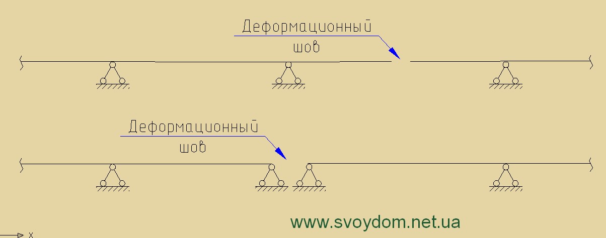
Multi-span beam supported on masonry walls.
![]()
Multi-span slab supported on metal beams.
Monolithic basement wall.

Connecting a reinforced concrete column to the foundation.

Hinge or pinch – which to choose?
Is the connection between the grillage and the piles a hinge or a rigid connection?
Supporting a metal or reinforced concrete frame on the foundation.
Floor slabs and beams.
Supporting end slabs or secondary beams.