
This article will talk about how create your own drawing frame for AutoCAD using a dynamic block. I advise you to understand this topic, since the skill of creating a dynamic block will be very useful to you. Using a dynamic drawing frame in autocad is much more convenient than using many different separate frame templates for different formats.
To begin with, what is it? dynamic frame. The idea is that by clicking on the frame, we can select the format we need and the frame will automatically adjust to the specified size (A4, A3, A2, A0 and others). The frame can also be stretched to an arbitrary distance by pulling a corner to obtain non-standard dimensions of the drawing.
This is what this one looks like dynamic block.
For example, you can download the AutoCAD frame I created and edit it.
But since each company needs to fill out its own stamp (starting with the company name...), I recommend creating your own template for the dynamic frame.
Let's start creating a dynamic frame with a stamp for drawings in the Autocad program.
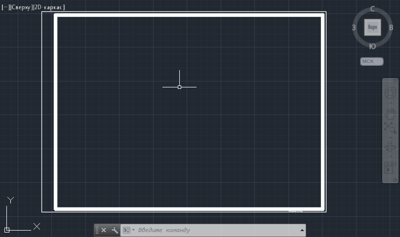
First, we need a ready-made format, preferably A3 horizontal size (the kind you use)
Select our format and click on the create block icon. 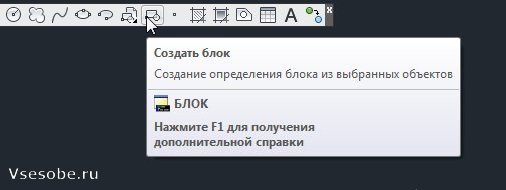
The following table appears. We fill in the name of the block, select the point of origin of the block (base point), the selected elements should contain our frame, and in the lower left corner there should be a checkmark to open in the block editor. Click OK. 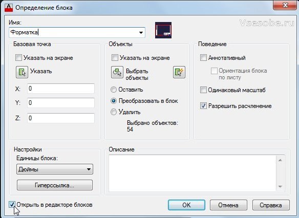
Our format has opened in the block editor, now we can create a dynamic block from it. 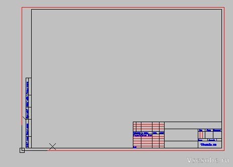
Let's indicate the parameters that can be changed. On the parameters tab, select linear. 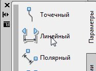
Let's indicate the vertical parameter (as if we were specifying the vertical size of the frame) 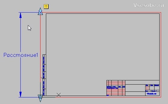
On the Operations tab, select Stretch. 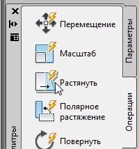
Select a rectangle for stretching, as shown in the figure. 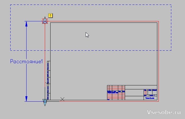
Selecting stretchable elements. 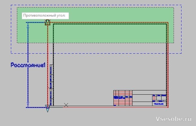
An icon should appear in the corner, indicating that a stretching operation has been set.
Now let's specify another linear parameter (distance2) for horizontal stretching. 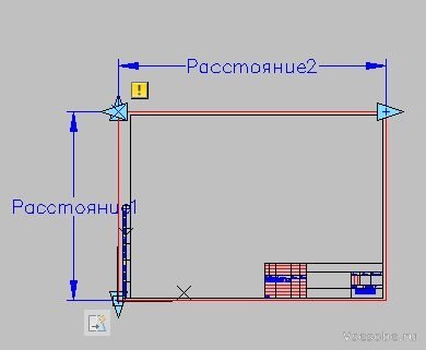
Let's perform the same stretching operation on it. Let's indicate the frame this way. 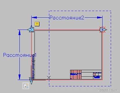
Specify the elements to be stretched. 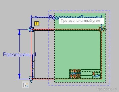
Now our format can be stretched to the desired size. You can check by saving the block. 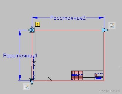
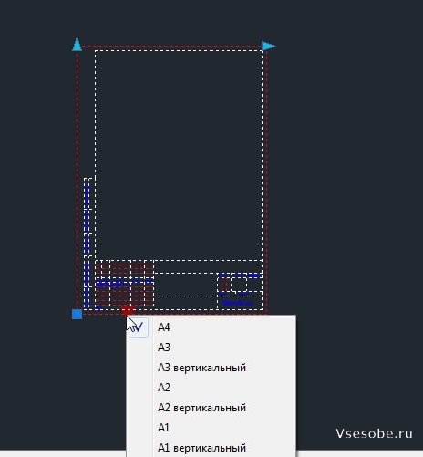
So that we can specify the required size of the drawing frame for AutoCAD (A0, A1, A2, A3, A4), we need to add the selection parameter. (Located on the parameters tab) 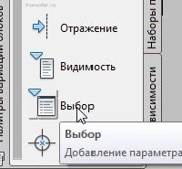
Let's indicate the location of the selection parameter icon in the corner of our drawing frame. 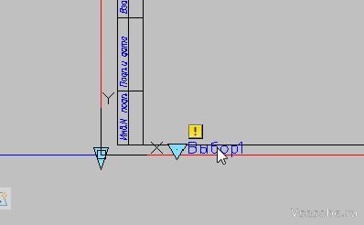
Double-click on the selection parameter to open the table. In the selection table, click add properties and add our linear parameters (distance1 and distance2). Then we fill out the table. On the left we indicate the required dimensions of the drawing, and on the right the name of the format (A0, A1, A2, A3, A4 and any others you use), the main thing is not to make a mistake with the dimensions. Click OK. 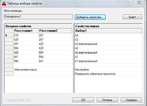
We can finish here. Our dynamic frame is ready. Click save block. 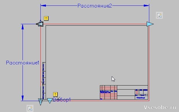
I’ll finish here, but you can further improve this frame using, for example, the visibility of objects, turning on and off the necessary elements (tables and others). You can also use changeable annotations to the dynamic block, thereby entering the desired text into the stamp, but I found this not very convenient (since it’s easier to copy the text into the stamp directly)
For those who have to constantly create drawings, it is useful to download and pre-install the AutoCAD program on your computer, which is an excellent tool for performing such tasks. ESKD standards require the presence of a frame on all sheets of drawings. It is for this reason that many novice users want to find out how to insert a frame into a finished or newly created drawing when working with software Autocad.
Working with the SPDS module
In the most AutoCAD program The SPDS module is built-in, containing a whole set of various frame contours that fully meet the requirements of GOST. In such cases, all the main inscriptions are already inserted into the frame, so there is no need to waste time drawing the object manually. It is also possible to select a frame contour with a stamp, which is specified in the technical specifications.
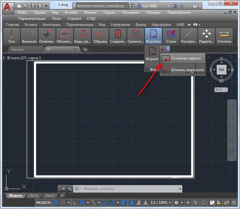
So, put aside unnecessary doubts, draw the desired frame using the SPDS module. On the toolbar, find the “SPDS” parameter, click on it. After these steps, an additional submenu will open below, in which find the “Format” option, click on it.
Now you need to select the size of the sheet on which you want to place the picture, frame outline. If you choose the wrong sheet value, you will get a less than impressive result. It is for this reason that you first decide what sheet format you need. After this, on the worksheet, indicate the insertion point of the desired graphic object. Now you can practically see that with the SPDS module it is very easy to place a frame.
Do not forget that most standard frame contours are necessarily accompanied by established inscriptions. Of course, you can again enter everything manually. However, if you are short on time, we recommend automating this task as well.
By clicking on the “Format” parameter, select the “Basic Inscriptions” sub-item, after which a window will open in which options for frequently occurring inscriptions will be listed. All you have to do is choose the option that fully suits the requirements of the task. And only after completing such actions can you print the drawing.
Removing frames
Unfortunately, sometimes we draw, due to our inexperience or misunderstanding of the conditions of the task, the first time we draw the wrong outline that is required. Accordingly, there is a need to figure out how to remove the frame if it turns out to be unnecessary or inappropriate. By the way, sometimes it becomes necessary to delete a graphic object that surrounds the inserted picture along the contour. We invite you to consider ways to remove any type of frame.
On the toolbar, find the “Edit” option, then select “Object”, then move the mouse cursor to “External Links”, finally click on the “Outline” option and disable it. Now the unwanted graphic will disappear from the worksheet.
So, we are confident that after reading these recommendations, you will be able to easily, as needed, add or remove frames and perform various technical tasks associated with creating new drawings.
A frame is a mandatory element of a working drawing sheet. The shape and composition of the frame is regulated by the standards of the Unified System of Design Documentation (ESKD). The main purpose of the frame is to contain data about the drawing (title, scale, performers, notes and other information).
In this lesson we will look at how to make a frame when drawing in AutoCAD.
The most trivial way to create a frame is to draw it in the graphic field using drawing tools, knowing at the same time the dimensions of the elements.
We will not dwell on this method in detail. Let's assume that we have already drawn or downloaded the framework of the required formats. Let's figure out how to add them to the drawing.
1. A frame consisting of many lines must be presented as a block, that is, all its components (lines, texts) must be a single object.
2. If you want to insert a ready-made block frame into the drawing, select “Insert” - “Block”.
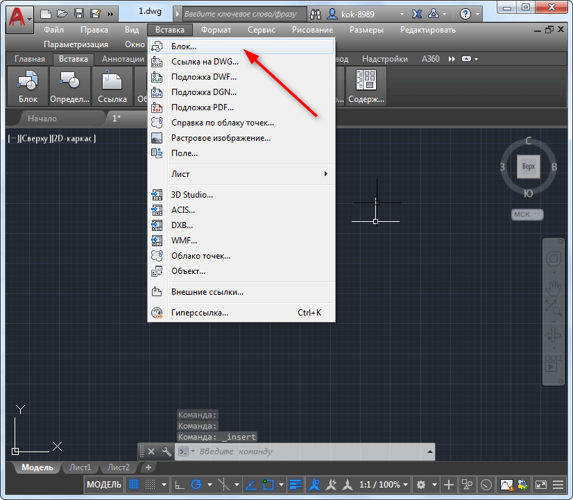
3. In the window that opens, click the browse button and open the file with the finished frame. Click OK.
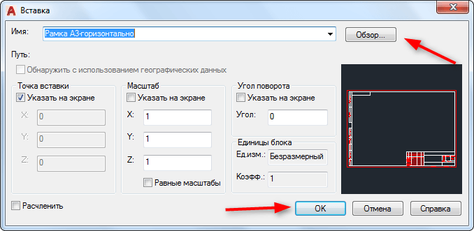
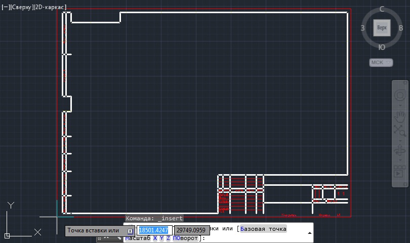
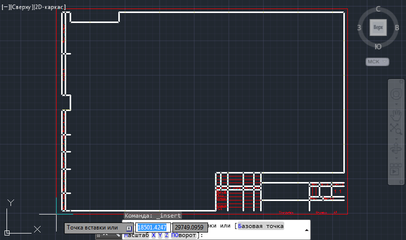
4. Determine the block insertion point.
Adding a frame using the SPDS module
Let's consider a more progressive way of creating frames in AutoCAD. IN latest versions This program has a built-in SPDS module that allows you to draw up drawings in accordance with GOST requirements. The frames of established formats and main inscriptions are an integral part of it.
This add-on saves the user from manually drawing frames and searching for them on the Internet.
1. On the SPDS tab, in the Formats section, click Format.
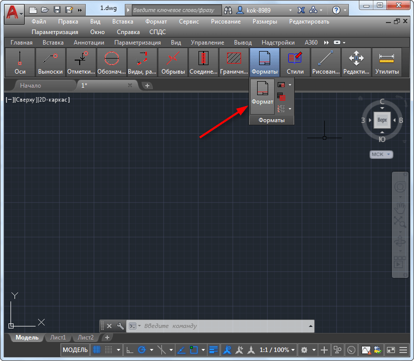
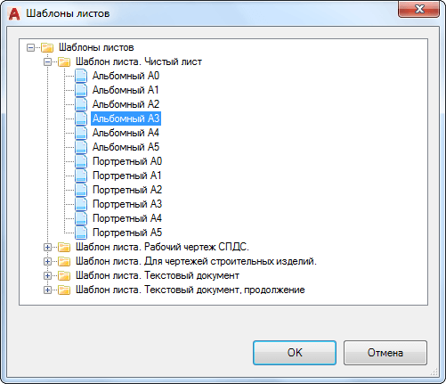
2. Select a suitable sheet template, for example, “Landscape A3”. Click OK.

3. Specify the insertion point in the graphic field and the frame will immediately appear on the screen.
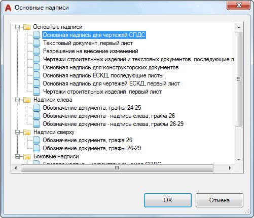
4. The title block with data about the drawing is missing. Under Formats, select Title Block.
5. In the window that opens, select the appropriate type of inscription, for example, “Main inscription for SPDS drawings.” Click OK.

6. Specify the insertion point.
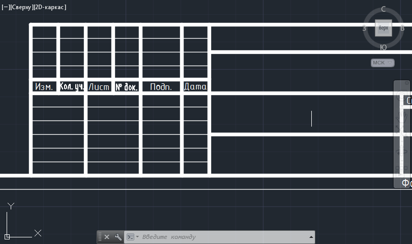
Thus, you can fill the drawing with all the necessary stamps, tables, specifications and statements. To enter data into a table, simply select it and double-click on the desired cell, then enter text.
So, we looked at a couple of ways to add a frame to the AutoCAD workspace. Adding a frame using the SPDS module can rightfully be called more preferable and faster. We recommend using this tool to prepare project documentation.