In conventional images of stairs, an arrow shows the direction of the rise of the flight. The circles at the beginning of the arrows and the ends of the arrows are placed at the edge of the floor area to which the plan belongs.
Rice. 24. Conditional image stairs in various scales according to GOST R 21.1501-92 (the arrow indicates the direction of rise of the flight).
2.8. Drawings of building plans.
Each symbol is drawn to the same scale as the rest of the floor plan. Labeling conventions. . By putting it all together and with a little intuition, most symbols can be worked out, but some are harder to understand. The scale will tell you if you are planning your floor plan in feet and inches or in the metric system. There is a scale of feet and inches at the top and a metric at the bottom. The North arrow shows you the orientation of the object.
Drawing building plans
The top line represents the outer wall and the bottom line represents the inner wall. Sometimes there is not much difference between external and internal walls. Walls can also be represented by a black outline rather than a solid line. The dotted square top left indicates something above the line where the floor plan is cut. It could be a missing ceiling. The dotted line could be a ceiling beam.
The building plan gives an idea of its size and shape in plan and relative position separate rooms. The building plan shows window and door openings, the location of stairs, partitions and main walls, built-in closets, sanitary equipment, etc.
If the plan, facade and section of the building can be placed on one sheet, then the plan is placed under the facade in projection connection with it.
The solid circle and square represent the columns. A black and white circle is used to indicate the height of the floor so you can tell if there is a step up or down. The picture below is a fireplace. Single doorDouble doorDoor deliveryRoad doorAdditional door.
There is a double-hung window at the top and one window underneath. There it is straight up, up and back towards you and around the corner. Then the stunning staircase style is revealed. Kitchen fittings and appliances. Kitchen countertop on top with a cupboard above. The solid line here represents the top of the kitchen counter with the dotted line representing the cabinet on top.
The plans indicate the names of the premises. These names can be given in the explication (table) of the premises (see Fig. 25); In this case, on the drawings in circles (for a plan drawing on a scale of 1:100, the diameter of the circle is taken to be 6 mm) the room numbers are indicated. The name of the premises is not indicated if their purpose is clear and without explanatory notes, for example, on floor plans of residential buildings.

Rice. 25. Explication tablepremises.
Dimensions are put down on floor plans, which make it possible to judge the size of all rooms and the dimensions of structural elements. The position of all structural elements on the plan is determined by reference to the coordination axes. On floor plans, external dimension lines are usually drawn to the left and below the outline of the plan. On the first dimension line, put down the dimensions of the door and window openings in quarters (“in the light”) and the dimensions of the walls between them. On the second dimension line, the dimensions between adjacent coordination axes are indicated, and on the third dimension line, the dimensions between the extreme axes are indicated.
The internal dimensions of the premises (rooms), the thickness of the partitions and internal walls are indicated on the internal dimension lines. The internal dimension line is drawn at a distance of at least 8...10 mm from the wall or partition. They also mark the binding of all main walls to the coordination axes.
The areas of individual rooms are indicated in the lower right corner of the plan in square meters with two decimal places and a bar at the bottom.
The binding is carried out by setting dimensions from the axis to the outer edge of the wall. In internal walls, the coordination axis is combined with the geometric axis (Fig. 26, axis B).

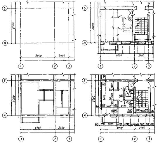
Rice. 26. Ground floor plan.
In the walls of staircases and in walls with ventilation ducts, the coordination axes are shifted from the geometric axis (axis 2 And 3 ).
In brick buildings, the thickness of the walls and the dimensions of the piers are multiples of the dimensions of the brick; the dimensions of a standard building brick are equal 250x120x65 mm(see Fig. 27).

Rice. 27. Standardbuildingbrick and fragment of brickwork.
Lifting from one floor to another is usually carried out along two flights. This staircase is called two-march. Since the floor plan is formed by a conditional dissection by a cutting plane drawn at the level of the window openings, in the staircase the ascending flight intersects approximately in the middle. On the plan, in this place, a double cliff line is drawn at an angle of 45°, the longer side of this part of the flight is adjacent to the wall of the staircase.
External doors- entrances from the street to the house (see part of the 1st floor plan, Fig. 26) according to fire safety requirements must open to the street, and doors from the stairs to the apartment should open into the apartment.
The opening of doors within an apartment is determined by its layout and the convenience of using the premises. If the door is located near a wall, then the opening is made towards the wall.
2.9. Drawing building plans.
The sequence of drawing a building plan is shown in Fig. 28.
The building plan is drawn in the following sequence:
Stage 1. Drawing the plan begins with drawing the coordination axes of the building, first longitudinal and then transverse. These axes are conventional geometric lines, which, in in some cases, may not coincide with the axes of symmetry.
The coordination axes of the building are drawn with dash-dot lines with long strokes (thickness from s/2 before s/3 ), are indicated by stamps in circles with a diameter of 10 mm for M: 100.
Then external extension and dimension lines are made.
Stage 2. Having constructed the coordination axes, draw the contours of the external and internal main walls and columns with thin lines (0.3 mm).
The binding of a structural element is determined by the distance from the coordination axis to the face or geometric axis of the element. In external load-bearing walls, the coordination axis runs from the internal load-bearing wall either as a multiple of the module, or half of it.
In brick walls, this distance is most often taken to be 200 mm, and in thin walls - the size of the module, i.e. 100 mm.
Stage 3. After drawing the external and internal main walls and columns, the contours of the partitions are drawn. Attention should be paid to the difference in the connection of external and internal main walls and partitions.
Perform window breakdowns and doorways and outline the contours of the main walls and partitions with lines of appropriate thickness (see above).
Window (OKI) and door openings (D1) are drawn in external and internal walls and partitions (they will depict a quarter in brickwork, and are not depicted in wall panels), conventionally show the opening of doors.
The plan also shows the symbol of stairs, sanitary equipment and the direction of opening doors.
Stage 4. Dimensions in mm are applied to the completed plan drawing.
The external dimensions located behind the plan dimensions represent three “chains”. Due to the fact that marks of various building elements are often placed in front of the first dimensional “chain”, in many design institutes it is customary to place them at a distance of 14 mm from each other. In the first “chain”, counting from the outline of the plan, there are dimensions indicating the width of window and door openings, piers and protruding parts of the building, linking them to the coordination axes.
The second “chain” contains the size between the axes of the main walls and columns. In the third “chain” the size is set between the coordination axes of the outermost outer walls. If the openings are located identically on two opposite facades of the building, it is allowed to apply dimensions only on the left and lower sides of the plan.
Horizontal traces of secant planes are also drawn on the plans, the areas of the premises are calculated and marked, and the numbers of the premises are indicated in circles according to the explication. Draw two internal dimension lines (horizontal and vertical) and end general design plan, observing the thicknesses and types of lines (see Table 2).
Rice. 28. Consistencydrawingplanbuilding
Calculate the staircase. The dimensions of the staircase are determined as a result of the calculation. In residential premises
flat stairs with a slope of 1:2 and medium ones with a slope of 1:1.75 are used. The staircase consists of landings and flights - inclined parts connecting the landings and consisting of steps. The step consists of a horizontal section - the tread and a vertical section - the riser. The dimensions of the steps are determined from the average human step according to the ratio 2h + b = 600 mm. The riser height can be selected from 150 to 180 mm. Tread width is from 270 to 300 mm. With a staircase slope of 1:2, the ratio h: b = 150:300, with a slope of 1:1.75 - h: b = 165:290. The number of steps in each march is no less than 3 and no more than 16.
In order to correctly and accurately draw a staircase on a section of a building, it is necessary to prepare a grid (Fig. 3.10). The grid consists of vertical lines located from each other at a distance equal to the width of the tread, and horizontal lines - at a distance from the height of the riser.
Example. Floor height H = 3000 mm, staircase slope 1:2, flight width 1200 mm. The width of the staircase is equal to the width of two flights and the space between them. Size m is 100-200 mm. We choose a two-flight staircase. Therefore, the height of one flight H/2 = 1500 mm. With a staircase slope of 1:2, the ratio h:b = 150:300. Let's determine the number of steps of the march H/2: h = 1500:15, i.e. 10 risers.
The length of the staircase L is determined from the width of the two landings and the size of the flight. The width of the platform is usually taken to be equal to the width of the march or greater, but not less than 1200 mm.
March layout L = b(h-1). The plan shows one less step, because the upper step is combined with the landing L = 2x1200+9x300 = 5100 mm. The plan of the first floor shows the basement and lower flight (Fig. 3.11). The thickness of the landing is 30-40 mm. Flights of stairs are protected by railings 900 mm high.
Rice. 3.10. Construction of a staircase on a section

Rice. 3.11. Building a staircase on the plan
It should be borne in mind that the cutting plane along the stairs always passes along the flights closest to the observer. Support nodes flight of stairs on landing and metal fencing are shown in Fig. 3.12.

Rice. 3.12. Nodes for supporting a flight of stairs on a landing:
a) top node; b) intermediate node
6. Apply dimensions. On the sections, the coordination axes are brought down, the corresponding marks are placed in circles, a dimension line is drawn and dimensions are applied above it. The position of the structural elements is determined
using elevation marks, which are placed on the level lines of the corresponding elements. Inside the section, the heights of floors and doorways, as well as elevations of floor levels and staircase landings are marked.
7. The names of sections indicate the designation of the corresponding cutting plane marked on the plan, for example: CUT 1-1.
Examples of the design of a task sheet are shown in Fig. 3.13, 3.14.


Nodes. Draw two structural units of the building.
Nodes are enlarged fragments of buildings, structures or their elements.
When performing nodes, the corresponding place is marked on the original image with a closed solid line thin line(circle or oval) with markings on the shelf with leader lines in Roman, Arabic numerals or letters of the Russian alphabet.
Dimensions are applied to the nodes indicating the nature of the connection of the component parts, the brand of elements, etc. For clarity, apply on the section symbols materials according to GOST 2.306-68 (Table 3.3).
Table 3.3
Sheet 3. Complete the façade of the building.
Facade. The facade of a building is usually called appearance front, side or back. Plans and sections of the building determine all the dimensions necessary for drawing the facades.