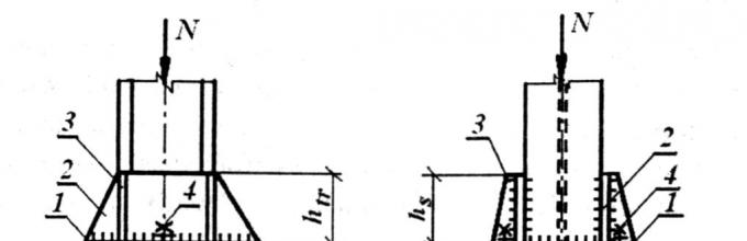
The base of the column serves to distribute the concentrated pressure from the column rod over the foundation area and ensures the fixation of the lower end of the column in accordance with the accepted calculation scheme.
There are two main types of bases - articulated and rigid. Hinged bases have the simplest design. For centrally compressed columns with significant force, a base consisting of a thick steel base plate, on which the milled end of the rod rests (figure below). For light columns, milling the end is impractical, since all the forces can be transferred to the base plate through the welds, with the help of which the column is attached to the plate. The connecting traverse (figure below) creates a more uniform transmission of the power flow from the column to the slab. The peculiarity of all hinged bases is that anchor bolts(there are usually two of them) attach the base to the foundation directly behind the base plate.
The results of the calculation turned out to be comparable in general and generally fall well within the accuracy of the calculation methods. As stated above, the design column diameter must be further refined by checking for column performance correlation. After this clarification, a possible choice of the column diameter will be made.
A Brief History of the Art of Distillation. On the distillation of binary mixtures. Oil refining industry. Volume 3, Homs, Syria: Al-Baath University. Examples of using the optimal reflux ratio of distillation towers in oil refining processes.
Rigid bases of centrally compressed columns (figure below) have at least four anchor bolts that are attached to the traverses. Due to this, after tightening the bolts, the rotation of the column on the support is excluded.
Rigid bases are arranged in eccentrically compressed columns, which can transmit bending moments. To this end, the traverses have to be developed in the direction of the moment. With relatively small support moments, the traverses are made of sheets 10-12 mm thick (like the figure below) or channels.
Fractional distillation in a lunar environment. Fundamentals of multicomponent distillation. How do the trays and packaging stack up? Equipment design and costs for the separation of homogeneous mixtures. Bangladesh University of Engineering and Technology, Dhaka. Calculation of calculations using hot keys through spreadsheets.
Data and methods for estimating preliminary capital costs. Conceptual design of chemical processes. Oil refining industry. Tank tower potential ignores trays. Recent advances in distillation. Davis-Swindin Memorial Lecture, Loughborough University.
Types of column bases
1 - anchor bolts; 2 - base plates; 3 - traverses
The thickness of the base plate is determined by calculation, however, for structural reasons, it is not taken to be less than 20 mm.
Typically, the bases of the columns are installed 500-1000 mm below the floor mark of the building and concreted to protect against corrosion.
Calculation and design of column bases. The base serves to transfer the load from the column rod to the foundation. With a slight load (N< 6000 кН) она состоит из опорной плиты, и на-грузка в этом случае передается полностью сварными швами, при-крепляющими стержень колонны к этой плите. В общем случае база состоит из опорной плиты 1, траверс 2, ребер жесткости 3 и анкер-ных болтов 4 (рисунок ниже). На этом рисунке представлен нежесткий (шарнирный) вариант базы. При назначении размеров элементов базы принимают во внимание рекомендации: с = 70-120 мм; t pl = 16-40 мм; t tr = 10-16 мм; t r >6 mm.
The Process Engineer's Pocket Guide. In fact, the term used in Arabic for fractional distillation is derived from this repetitive evaporation-condensation cycle. In thin layer chromatography, the stationary phase consists of a thin layer of adsorbent deposited on a flat support such as a glass plate or an aluminum or plastic sheet.
This process is similar to paper chromatography with the advantage that it develops faster, provides better separation, and can be selected from a variety of adsorbents. A small amount of the problem sample is deposited in solution at a point on the bottom of the plate. The plate is then introduced into the chromatographic cuvette so that only the bottom of the plate is immersed in the liquid.
Base scheme
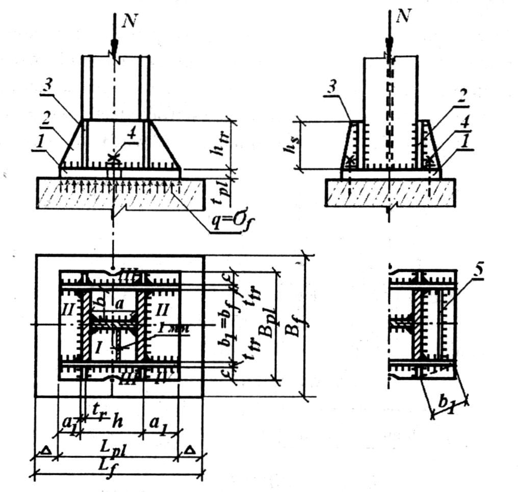
1 - base plate; 2 - traverses; 3 - stiffeners; 4 - anchor bolts; 5 - diaphragm
Anchor bolts fix the correct position of the column relative to the foundation. In centrally compressed columns, they have no effort, and therefore their diameter is set constructively in the range of 20-36 mm. With hinged support, the anchor bolts are attached directly to the base plate (figure above), due to the flexibility of which the connection is pliable if random moments occur. With a rigid connection, bolts (at least four) are attached to the column rod by means of special tables or to traverses (in buildings with light overhead cranes) and tighten them with a voltage close to the design resistance. This eliminates the possibility of turning the column rod on the support. In this case, the base is considered to be rigidly fixed in the foundation of the building both in the plane and out of the plane of the frame.
When the eluent passes the spot where the problem mixture is located, a balance is established between the molecules of each of the components in the adsorbed mixture and the solutions in the solution. In principle, the components will differ in solubility and their adsorption strength, so that the components will move more than others. When the eluent reaches the top of the plate, it is removed from the cuvette, dried and the separated components of the mixture are removed.
If the compounds are colored, the spots can be observed with the naked eye. If not, there are several ways to visualize spots corresponding to each component of the mixture. Typically, a fluorescent dye is added to the adsorbent so that the plate fluoresces everywhere except when there is a spot corresponding to an organic compound. Use developers, for example, iodine vapor, which are non-specific reagents.
- Use ultraviolet light to observe the plate.
- Use special reagents to develop color stains.
Rice. 4.17. Head of a through column
The heading calculation is reduced to:
1. Determining the thickness of the vertical rib.
2. Determining the height of the vertical edge.
The thickness of the rib is determined from the calculation of the rib for collapse.
Crushed surface area:
– design resistance of steel to crushing
Estimated rib width:
The sample to be separated is deposited at the top of this support. The rest of the column is filled with eluent, which, by the effect of gravity, moves the sample through the column. A balance is established between the dissolved solution adsorbed on the stationary phase and the eluting solvent flowing through the column. Since each of the components of the mixture will establish different interactions with the stationary and mobile phase, they will be transported with different speed, and their separation will be achieved.
Thus, similar to other types of chromatography, differences in the rates of movement through a solid medium correspond to different times elution at the bottom of the column for each of the components of the original sample, which are collected in different fractions. The polarity of the eluent affects the relative speeds at which the different components of the mixture move in the column. Polar solvents compete more effectively with polar mixture molecules for polar adsorbent locations. Therefore, a polar solvent quickly moves molecules, including more polar molecules, through the column.
![]() - width of the supporting ribs of the beams
- width of the supporting ribs of the beams
![]() - head base plate thickness
- head base plate thickness
Fin thickness ![]()
We accept the thickness of the ribs ![]() .
.
If the solvent is very polar, the elution will be very fast and there will usually be little separation of the components of the mixture. If, on the contrary, the solvent is very non-polar, the column compounds will not elute. Therefore, the choice of eluent is critical to the success of column chromatography. An increasing polarity gradient is often used for elution.
The difference with traditional column chromatography is that in fast technology, the solvent is passed through the stationary phase by applying positive pressure. This improves the separation resolution and the elution time can be shortened, making it the method of choice.
We set the leg of the seam k f \u003d 10 mm
Welds will be performed by semi-automatic welding with E42 electrodes made of solid wire Sv-08A with a value 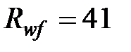 kN/cm2. For steel C255 value
 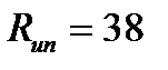 kN/cm2.
Analysis of column eluates. If the compounds separated by column chromatography are colored, then the separation process can be monitored visually. However, the compounds to be isolated are often colorless. In this case, fine fractions of the eluates are sequentially collected in labeled tubes and the composition of each fraction is analyzed by thin layer chromatography. After identifying different fractions containing the same product, the solvent is removed and the identity of the components is analyzed using spectroscopic methods.
steel columns and concrete foundation. The base slab receives the weights of the steel column and distributes them in a larger area of concrete located under said slab. Forces distributed over the entire area of the plate, which, in turn, exert pressure on the concrete, which in turn reacts in the same way with equal pressure, but in the opposite direction. This tends to bend the cantilever portions of the plate. Base plate critical bending occurs at distances between 80 times the width of the column flange and 95 times the depth of the column wall.
Coefficient values 
Thus, the calculated resistances of the weld for the weld metal and for the fusion boundary, respectively, will be equal (according to Table 3 of SNiP II-23-81 *):
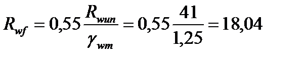 ; kN/cm2.
The maximum moments occur with respect to the specified axes, as shown in the figure. Two axes are parallel to the soul, and two are parallel to the skates. The main axes of any of the times adjust the design to determine the thickness of the base plate. When the column is subjected to high intensity bending. Case 3 is usually found in rigid frames where the shear is often small. The latter are steel rods embedded in the foundation and secured to the base plate with nuts and washers that should not be brazed unless they are designed to resist shear.
Coefficient values when welding in the lower position are equal:
Therefore, the design cross section is the metal cross section of the fusion boundary. Then the length of one fillet weld will be equal to (at k f = 10 mm - for inserting the wall into the column > 10 mm).
Case 1 is a column with axial load. Such a moment can be resisted by developing a couple of forces that are generated by concrete and anchors. The design of the anchors is of paramount importance as they are responsible for resisting tensile forces and transmitting shear to the concrete. The diameter of the anchor rods must be sufficient to prevent their failure, and the depth must be sufficient to prevent the anchors from sagging. bending and shear moment.
In addition, soul crush and soul flow do not affect the design of pillar base plates. the back pressure is then concentrated near the column profile. If the slab covers the entire concrete surface. Composite columns are elements of compressed concrete reinforced with a longitudinal profile or steel pipes. In composite columns with structural profiles embedded in concrete, longitudinal bars are used in the same way. Built-in columns should offset the cost of the box with steel savings. these composite sections carry more load than reinforced concrete sections of the same size. increased stiffness and in some cases deprivation or stiffness against the local bending section. at certain distances to prevent longitudinal deformation of the longitudinal rods. in some cases shear bolts are welded to the steel profile to complete the compound action. in addition to the contribution of a particular element to the mechanical work in compression.
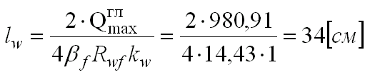
We accept h p \u003d l w +1 \u003d 34 + 1 35 cm
The height of the rib is equal to the total length of the seam l = 35 cm = 350 mm
Calculation and construction column bases.
The calculation comes down to:
1. Determination of the required area of the base plate and its dimensions in the plan.
2. Determining the thickness of the slab.
These minimum values are given to prevent local buckling. - The steel profile must be reinforced with longitudinal and lateral rods. The area of the structural steel profile must be at least 4% of total area cross section of the composite section. The required amount of longitudinal and transverse reinforcement is considered sufficient to prevent crushing of the concrete surface during a fire. because if it is less than the specified one, the section will be designed as a reinforced concrete column.
If the yield strength of steel. After the concrete has hardened. Respectively. coefficient of reduction of support resistance in concrete. When multiple columns contain more than one steel profile. resistant to concrete, must be developed by direct support in joints. This first version of these Structural Design Notes is a bibliographic collection of textbooks, technical articles, and design rules related to the topic of structural steel using the load and resistance design philosophy, and is not intended to replace said materials in this document. In this sense, the purpose of these notes is to provide the reader with a compendium of such material and, therefore, not to go into depth during the development of topics. The purpose of these notes is to periodically review them and introduce new design concepts for metal structures. For many desirable characteristics, structural steels have led them to be used in a wide variety of applications. They are available in many product forms and have a high intrinsic strength. They have a very high modulus of elasticity so that deformations under load are very small. In addition, structural steels have greater ductility; have a linear deformation strain even at relatively high stresses, and their modulus of elasticity in tension, as in compression, is the same. Therefore, the behavior of structural steels under working loads can be accurately predicted by the theory of elasticity. In addition, since they are produced under "control" conditions, they guarantee uniform quality. Structural steels include a large number of steels that, due to their economy, strength, ductility and other properties, are suitable for participants who are loaded into various structures. Variable resistance levels are obtained by changing the chemical composition and heat treatment. Structural steel deformation deformation diagram If a piece of sweet structural steel is subjected to a stress test. Typical stress-strain curve for mild steels. When the tensile stress reaches about 50% of the ultimate strength of the steel, the elongation will begin to increase more rapidly without a corresponding increase in stress. The greatest force for which Hooke's law is still valid and which the material can withstand without permanent deformation is called the proportional limit and elastic limit, respectively. Structural Steel Design Victor Escalante Cervera The force at which there is a sudden increase in elongation or deformation without a corresponding increase in force is the yield point. This effort is the most important property of steel, as many design procedures are based on this value. Within this limit, there is elastic deformation. In addition to this value, there is an interval in which an increase in deformation occurs without an increase in force. This deformation is known as plastic deformation, which is ten to fifteen times the elastic deformation. After the plastic area, there is an area called work hardening where additional stresses are required to produce large deformations. 2 Modern structural steels Table 1 Structural steel properties. These steels have the key elements of carbon and manganese resistance in carefully metered amounts. Carbon steel are those that have the following elements with maximum amounts: carbon 7%, manganese 65%, silicon 60% and copper 60%. It is the most used structural steel. Inch is suitable for bridges and bolted or welded structures. High strength and low alloy steels. These steels obtain high strength and other properties by adding columbium, chromium, vanadium, nickel in addition to carbon and manganese. The term limit state is used to describe the condition under which a structure or part of it fails to perform its intended function. There are two types of limit state: resistance and maintenance. The former are based on the safety or loading of structures and include ductility, bending, fracture, fatigue, tip, etc. resistance. Structural steel construction Victor Escalante Cervera Second refers to the behavior of structures under normal loads and refers to aspects related to use and occupation such as excessive booms, landslides, vibrations, etc. strain strain curves for different types of steel. The structure must not only support the design loads, but also the maintenance load in such a way that the requirements of the users are met. The structure is designed in such a way that it has an ultimate structural strength sufficient to withstand factorized loads. This is one with a profile strong enough to be able to develop a general plastic stress distribution before buckling. The term "plastic" means that in all sections the flow stress is present and will be studied in chapter 4 of these notes. This is one in which a creep force can be achieved in some but not all of its elements for compression before buckling; he cannot achieve a complete plastic distribution of forces. Strict elements for compression. For these elements, it is necessary to take into account the resistance to elastic buckling. In general, the tension design is the simplest, as there is no buckling problem, it is only necessary to calculate the factorized force that the member must accept and divide it between the design forces to obtain the required cross-sectional area. The types of profiles used to design tension elements are shown in the following figure. For the creep limit state in the shaft section. For rods and round rods. Calculation of Net Areas Defined as the total cross-sectional area minus the area of grooves, cutouts or holes. When considering hole area, subtract an area slightly larger than the nominal hole. For high-strength screws, increase the screw diameter by one-eighth of an inch. The area subtracted by the holes is equal to the area of the holes over the thickness of the metal. When having more than one row of screw holes in an element, it is sometimes desirable to place holes in the holes in order to have the maximum mesh area in any section to withstand the load. Figure 2 Alternative Holes Due to the concentration of shear forces near the joint, members subjected to axial tension show a reduction in tensile strength. In this case, the flow of tensile stresses between the cross section of the main element and the element with the smaller element connected to it is not 100 percent efficient. Bolted connections or notes Page Page 19 of 172 Metal Structure Design by Victor Escalante Cervera 3 Selection of profiles One of the criteria for selecting the profiles of elements subjected to tension is the calculation of the total minimum area, which must be equal to the area of \u200b\u200bthe mesh plus the calculated area of the holes. The purpose of these restrictions is to ensure that such elements have sufficient rigidity to prevent lateral deflection or excessive vibration. In addition, it is possible to imagine the case of voltage inversion in these elements during transportation and assembly or exposure to wind or earthquake. The specifications state that such "random" compressive forces should not exceed 50% of the compressive strength of the elements. On the other hand, we will see in the next chapter that for flex factors greater than 200, the calculated compressive stresses are very small. 4 Cutting block The structural strength of a stressed member is not always determined by Equations 1 or 2, or by the resistance of the fasteners or by the welding to which the member is connected. This can be determined by the strength of its shear block. Metal Structural Design Victor Escalante Cervera Element mismatch can occur along a stress path in one plane and move in another perpendicular plane. It is unlikely that a fracture will occur on both planes at the same time. It is logical to assume that the load will lead to the achievement of creep resistance in one plane, while in the other plane the excess has already been exceeded and the gap will be reached. It does not seem reasonable to add strengths in both planes to determine the shear block strength of a particular element. Block of cutters. Figure 2-4, in terms of shear block and small stressed area, and its main resistance to shear block failure is shear rather than tension. Thus, the design of the shear block is determined by first calculating the tensile strength in a section of the mesh in one direction and adding to this the value of the creep shear strength in the total area of the perpendicular segment; secondly, by calculating the shear tensile strength in the total stressed area and adding to this value the tensile strength in the net area of the shear perpendicular segment. The strength of the shear block is the highest value determined in both cases. Designing Members in Axial Compression 1 Introduction A column is a member that supports axial compression. This load may be concentric, that is, applied along a centroidal or eccentric axis, when the load is applied parallel to the axis of the centroidal element, but at some distance from it. Differences between members in tension and compression: Tensile loads tend to hold the members in a forward direction, while compressive loads tend to buckle them out of the plane of the loads. The presence of screw holes in the tension elements reduces the available areas to resist forces; in compression elements, it is assumed that the screws fill the holes, and the areas are available to resist loads. Profiles used in compression. Euler's formula, valid only for long columns, calculates the critical bending load. This is the maximum load that can support a long column. The concept of effective length is a mathematical artifact for replacing a column with any condition on its end with an equivalent column with its articulated ends, in order to apply Euler's equation. The strength of a column and the way it fails depends largely on its effective length. The greater the element's flex factor, the lower the load it can support and the lower the buckling force. If the coefficient of elasticity exceeds a certain value, the bending forces will be less than the proportional limit of steel. Columns in this range are incompatible. They can be divided into three types: short columns, intermediate columns, and long or thin columns. Short columns fail by crushing. Long columns fail in bending and intermediate columns fail in combination with bending and crushing. The slenderness ratio measures the tendency of the column to sag. The greater the coefficient of elasticity of the limb, the less the load that it can withstand. Most bars tend to fail in the inelastic range, while the nomograms were created with elastic conditions in mind. If this value is very different from the value calculated in step 1, another column is selected and the following steps are repeated. The lengths of the welds must be at least equal to the maximum element width. The connecting screws must not extend longitudinally more than 4 diameters between centers and the connection must extend at least 5 times the maximum width of the element. Note. The structural strength of a reinforced column is reduced if the distance between the connectors is such that one of the components of the column can be fastened before colliding as a whole. In addition to the grid, it is necessary to place connecting plates as close as possible to the ends and at intermediate points if the grid is interrupted. The grating consists of flat rods, but can sometimes be formed with corners, covers perforated plates, channels and other layered profiles. The maximum elasticity ratio is 140 for a single grid and 200 for a double grid. If the distance between connecting lines is greater than 15 inches, a double grille or a single grille must be used. In double symmetrical sections, there is an independent bend or buckle, since the load usually passes through the shear center outside the section. It is recommended to install stiffeners on both sides of the network at the point of application of the load. If the ends of the beams are located directly on concrete or masonry elements, it is necessary to distribute the ray reactions using supporting pillars or supports. We know from material mechanics that each beam cross section has a pair of principal and orthogonal axes for which the product of inertia is zero. bending occurs in relation to any other axis, different from the main, asymmetric bending. The tensioners make the spars continuous in the direction of their axes, and the moments about these axes are greatly reduced, as shown in Figure 4. The thickness commonly used for this type of section is a 10 gauge tensor, in addition to reducing the moments on the weak axis of the belts, provide lateral support to the belts, and also very useful for ensuring alignment with the belts during assembly until the roof is installed and connected to the spars. Horizontal cut between slab and beam. If the beam is completely embedded in the concrete, the two elements will work as a unit, provided they meet certain conditions. That is, the transfer of the horizontal shear force is carried out both by adhesion and friction between the beam and concrete, as well as by the shear force along the broken lines shown in the figure. shear resistance, some type of steel reinforcement is provided along the sections indicated by oblique lines. The concrete cover on both sides of the beam must be at least 2 inches. The coating must be at least 1 ½ inches on the top edge of the beam and 2 on the bottom edge. Concrete must have suitable reinforcement in place to prevent cracking in critical areas. On the other hand, mechanical adhesion can be established with shear connectors where the slab acts as an integral part of the beam and this structural deck system is known as composite beams. They are usually built using a concrete slab formwork that rests on beams. If the steel beam is supported on studs so that they will not be removed until the concrete has reached sufficient strength, dead and live loads will resist the composite section. It is common practice to use cold-rolled steel shells that function as concrete formwork and withstand floor loads. Exist different types configurations and transducers on the market, and manufacturers provide tables and aids to select the type of deck required. These rays are analyzed using the transformed cross section of the concrete slab in the equivalent area of steel. The effective drift width of the slab depends on the type of specification used. Quarter cleaning beam, Distance between centers support beams, 12 times the plate thickness, and for edge beams. The twelfth part of the beam is cleared. Half the distance to the axes to the next beam of supports, 6 times the thickness of the slab. The effective width of the compression skid of the composite section. Alternative design methods: The beam can be calculated if the steel section supports loads before the concrete is set, unless they are supported during the construction process so that the composite section supports all loads acting after the concrete is set, The steel section can be designed so as to withstand a positive moment due to all loads; if this method is used, no binding is required. 10 Construction of beams with transverse connectors Figure 4 Stress distribution in a composite section Most composite beams are constructed with shear connectors, Figure 6 shows the bending stress distribution of a composite section in which the neutral axis can be located either in the slab or in steel beam. So, wherever the neutral axis of a section is, it is relatively difficult to define a composite section. The deflection is calculated using the usual formulas. However, due to the influence of the plastic flow of the concrete, the deflection due to long-term loads must be greater than the calculated values based on the properties of the transformed section used to evaluate the force. It is not possible to achieve the full action of a compound section, either because there is not enough space to accommodate shear connectors or economy. Where this occurs, slightly larger steel profiles can be used and the number of shear connectors required for the full operation of the composite section can be reduced. 13 Cold formed steel cover considerations The following figure shows examples of metal composite deck sections. In order for the beams to support these types of roofs and be designed as composite beams, the following basic requirements are met: The nominal height of the corrugation rib must not exceed 3. Metal deck rib types. The thickness of the slab above the steel deck must be greater than 2. For this type of shell, shear connectors must not have a diameter greater than ¾ and must protrude at least 1 ½ above the height of the roof rib. If the roof ribs are perpendicular to the longitudinal axis of the beam, the concrete below the top rib is neglected for design purposes, but if the ribs are parallel to the beam, then the entire thickness concrete slab . If the deck cantilever is greater than or equal to 1 ½, the average rib width must not be less than 2 if plain asparagus is used. If more than one stud is used, the rib width will be greater than 2 plus 4 times the stud diameter. The head diameter is usually ½ inch larger than the stud diameter. The other end of the stud is welded to the beam frame. Longer length asparagus can be used if the slab is mounted on a beam and the connectors can only penetrate 1½ inches into the slab. Concrete cover on connectors must be at least 1 in any direction. There are also shear connectors formed by channels with one ridge strangled in the slab and another soldier on the ridge of the beam. Disconnector types. However, for practical purposes, this distance can be changed at large intervals and is constant within this interval. In the case where fatigue must be considered, as in bridges, the distance between connectors will be measured taking into account the fatigue strength of the connectors and the corresponding shear spacing. The minimum distance between the axis of the pin connectors along the longitudinal axis of the beam is 6 diameters, and the transverse direction is 4 diameters. If a metal deck is used, the minimum allowable distance is 4 diameters in both directions. When the steel beam slide is very narrow, it may be difficult to achieve the required minimum transverse spacing. In such cases, the asparagus can be placed alternately. If the deck ribs are parallel to the steel beam and more connectors are needed than can be accommodated inside the rib, splitting the deck is allowed to allow enough space. Shear connectors must be able to withstand both vertical and horizontal movements, as there is a tendency to separate vertically between beam and slab, as well as to slide horizontally. The asparagus heads help prevent vertical separation. In addition, it is specified that the maximum distance between the connectors should not exceed 8 times the thickness of the plate. The equations are based on experimental results. Lightweight concrete is commonly used in floor systems in multi-level buildings to reduce dead load. To calculate deflections under service loads in composite sections, it is necessary to calculate the value of the moment of inertia. Calculation of the moment of inertia of the composite section. For example, an architect may indicate the maximum possibility in their plans for the beams of a building. In the bridge, the ledges of the board can be limited to the required clearance. These coatings can be cut where the moments are smaller, saving some. A possible solution for this type of beams is: Fix the camber and place it on plates with a cover. Choose the largest standard profile that allows the plate to cover the plates in the top and bottom ridges and thus determine the dimensions of the covers. This difference is in regard to the flexibility of their souls. Although these sections, with their non-stiffened showers, are heavier than the same clearing arms and loads, their overall costs are sometimes lower due to their lower production costs. They must have simple or double symmetry and be loaded into these planes. When bending around their main axis, the lengths without lateral support of their compressed ridges in areas of plastic joints associated with failure mechanisms should not exceed the values \u200b\u200bspecified. plastic module of the entire beam is equal to the static moment of the compression regions and the stress of the core with respect to its neutral axis. After writing this expression, the area required for one of the skates can be cleared. Types of Reinforced Grating As already noted, laminated beams are usually compact, so local bending and shearing problems are not likely limit states. But an effective section may require a shower with a sufficiently large thickness factor that produces bending by bending or shearing or both, until creep in the skates is achieved. Elastic bending combined with elastic shear buckling. It is commonly referred to as a normal bend. Elastic bending combined with shear strength after deformation. Flexural stability after bending combined with elastic shear buckling. Bending resistance after bending combined with shear strength after longitudinal deformation Figure 4 The core acts as a reinforcement with stress diagonals and is able to withstand additional shear forces. The diagonal soul bar acts similarly to the parallel cord truss diagonal. The stiffeners act as struts that prevent the skates from joining together and the skates in turn prevent the stiffeners from attaching. The intermediate stiffeners, which are expected to withstand the load before initial buckling, thereafter withstand compressive loads due to diagonal tension. 21 Peralta Proportions of Armed Works. Condition Notes Page 90 out of 172. Presentation. . The main bases of the columns are: distribution of the concentrated pressure of the column spindle on a certain area of the foundation; and ensure the connection of the lower end of the shaft of the base spindle in accordance with the adopted structural system.
3. Determining the height of the traverse.
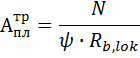
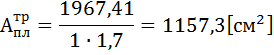
1) Required base plate area:
Design resistance of concrete to crushing
The base plate of the column base is attached to a concrete or reinforced concrete foundation using anchor (foundation) bolts.
Coefficient depending on the nature of the distribution of the load from the column over the area of collapse
Because we have uniformly distributed load(in the first approximation),
0.85 kN / cm 2 - the design resistance of concrete to compression, which is accepted according to SNiP "Concrete and reinforced concrete structures» according to the class of the given concrete (in our case B15).
- coefficient depending on the nature of the support of the base plates on the foundation and on the class of concrete. For concrete class below B25,
The coefficient of conversion of the design resistance of concrete to compression to the design resistance of concrete to crushing, which also depends on the class of concrete. In our case
We first determine the dimensions of the base plate in the plan, assuming that it is square.
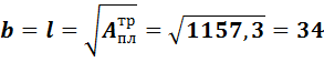
We take the dimensions of the slab, m (for structural reasons, so that the consoles are equal to their minimum value of 80 mm), then
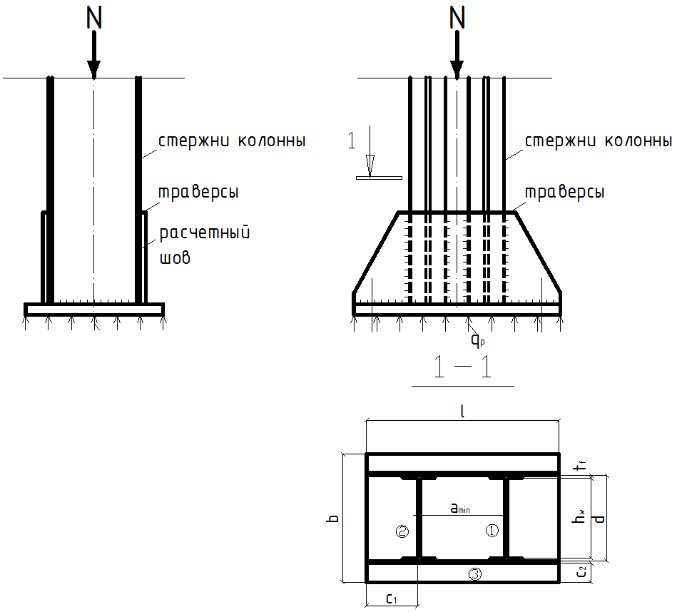
Rice. 4.18. Through column base
2) Determination of base plate thickness:
The slab works in bending from the reactive pressure of the foundation concrete applied to the slab from below.
We calculate the plate as a thin plate. To do this, we divide it into sections 1, 2, and 3 (Fig. 4.17).
1 - calculated as a plate embedded on four sides.
2 - as a plate embedded on three sides
3 - as a cantilever plate (plate)
Maximum bending moment in section 1:
- the smaller side of the lot
α \u003d 0.055 - coefficient taken according to the table of the method of elasticity and depending on the aspect ratio of the section ![]()
![]()
Accepted area by rounded dimensions
· The maximum bending moment in section 2 is calculated as for a console or as for a plate embedded on three sides.