K category: Partnerships
The road network of the village
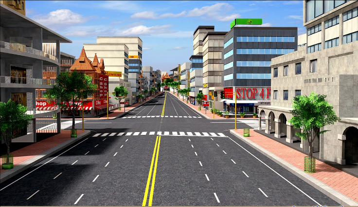
The road and transport network of the village includes main and secondary roads, parking lots and turnarounds, pedestrian and bicycle paths. The network of streets, driveways and footpaths of the village should be as simple as possible in outline, correspond to the directions of the main pedestrian and transport links, and provide convenient and short communication with the external road network.
The main passages serve for intra-settlement transport and pedestrian links, for connecting groups of residential buildings or quarters with other areas of the village. The main driveways are laid with a width of 6 ... 10 m (5 m - carriageway, 1.5 ... 3 m - roadsides with a ditch and a footpath). Residential buildings can be located no closer than 3 m from the border of the road (the red building line). On narrow passages after 100 m, passing platforms are arranged for oncoming cars. If parking is supposed to be on one side of the road, then the width of the pavement must be at least 5 m.
Secondary driveways are laid inside the residential group for access to residential buildings. Secondary passages are arranged as dead ends (with turnarounds at the end) or loopbacks, but in such a way as to exclude transit traffic along them. The length of the passage depends on the number of houses, the type of pavement, the width of the passage, the number of turns and the number of cars. No one likes when there is heavy traffic near the house, as this is associated with both noise and the danger of being hit by wheels. According to preliminary estimates, it can be considered that the passage is safe if it is used by no more than 50 cars per day. The width of secondary passages is 6 ... 8 m (2.6 ... 3.5 m - the carriageway, 1.5 ... 2.5 m - the roadside).
Crossing roads is the safer, the fewer directions converge together, the fewer left turns, the less traffic. Traffic becomes easier and more efficient if it is organized by one-way parallel passages. Experience shows that the number of traffic accidents is reduced if T-junctions are used for crossing roads, rather than four-way intersections (Figure 5).
Rice. 1. Cross profile of the main street with a boulevard
Rice. 2. Cross profile of the residential street of the village
Rice. 3. Cross profile of driveways
Rice. 4. Variants of the cross profile of country roads
Rice. 5. T-junction
Rice. 6. Parking at the T-junction

Rice. 7. Two-Way Car Parks
Rice. Fig. 8. Micro parking lots: a - transverse profile of a buried parking lot; b - plans for one-way car parks
Parking lots should be provided at the entrance to the village and additional ones along the driveways based on 2…3 guest cars for 5…7 houses. The optimal number of cars in the parking lot is 5…7. More machines violate the human scale of space. Parking lots should be covered with green hedges, trees, relief folds (Fig. 6…8). Passing and turning areas cannot be considered as parking lots.
The road surface depends on the traffic load. When driving more than 100 vehicles per day, a two-lane hard surface with a total width of 6 m is arranged. The hard surface of village driveways can be unpaved or asphalt. Concrete and asphalt have an adverse effect on environment. Solid coatings destroy the microclimate, take away from plants solar energy, they are unpleasant to walk on and dangerous to play with, plants and animals struggle to survive in such an environment. Concrete and asphalt pavements are appropriate only on main driveways and streets with public transport traffic.
The best solution for local driveways can be considered grass or dirt pavement with slabs laid in those places where the wheels of the car pass (Fig. 9). In summer, in sunny weather, the temperature over grass is 10 ° lower than over asphalt; in rainy weather, such a road dries out faster, and in winter, snow rolls cover any surface.

Rice. 9. Double track small slabs
Rice. 10. Outskirts of the village
Roadsides and parking lots can have a mesh covering of openwork slabs. Crushed stone and sand are laid on the turntables to strengthen the coating.
The main entrance to the village marks not only the border of the settlement, but also divides the territory with different social status. At all times, the entrance had an architectural interpretation, emphasizing its place in the figurative structure of the environment. The entrance can be decorated with gates, a bridge, pylons, small architectural forms, sculpture and other structures that mark the fact of crossing the border, make the living environment more meaningful (Fig. 10).
Bicycle paths are combined with the passage or laid in parallel, separating it from the carriageway with a lawn strip (Fig. 11).
The movement of a bicycle along local driveways and alleys is not difficult. A certain danger to a cyclist is created by standing cars, which impair the view of the road and occupy carriageway. In order to improve the safety of cyclists, local driveways should provide parking on only one (shady) side of the driveway, leaving the other (sunny) side for pedestrians and cyclists. There,
where the presence of cyclists is undesirable, it is enough to arrange a few steps and make a detour.
Schools, shops, public buildings are equipped with parking lots for bicycles.
Pedestrian links form their own system of roads within the village. For safety reasons, it is better to separate the movement of pedestrians and vehicles, especially where there is heavy traffic.

Rice. 11. Network of bike paths

Rice. 12. Scheme pedestrian roads between parallel passages 1 - roads; 2 - parking lots; 3 - pedestrian alley; 4-plots
The following methods of interaction between pedestrians and vehicles are possible: □ The main passages run parallel to each other at a distance of 100…150 m, and between them there are pedestrian paths and driveways to houses. Where pedestrian and transport roads intersect, small pedestrian areas are arranged (Fig. 12); the system of passages and pedestrian connections is built on the basis of lattices shifted relative to each other so that pedestrian and transport roads only intersect, forming pedestrian intersections (Fig. 13); dead-end green passages perfectly combine the functions of a driveway, a path and a playground (Fig. 14).

Rice. 13. Planning structure
Rice. 14. Organization of development around a dead-end passage: 1 - main road; 2 - dead end passage; 3 - plots; 4 - paths
The width of the footpath is taken at least 1 m, the width of the sidewalk - at least 1.5 m.
The runoff of surface water is carried out along the streets and roads with a hard surface. In this regard, it is undesirable to lay streets parallel to horizontal lines, since the natural flow of water is hindered. Laying streets across the horizontal is possible with a calm terrain, in otherwise, with steep terrain, this leads to an increase in the volume of earthworks and excessive steepness of the streets. Least allowable slope streets are accepted within 0.3 ... 0.5%, and the largest - 6 ... 8%.
The road network of the village
Introduction date 1998-09-01
DEVELOPED BY NIIMOSSTROY
INTRODUCED by the General Plan Development Department
APPROVED by the First Deputy Head of the City Prospective Development Complex E.V. Basin on August 7, 1998
Technical recommendations on the design and technology of construction of roads, sidewalks, sites in the territories of cultural and community purposes were developed by candidates of technical sciences V.M. Goldin, L.V. Gorodetsky, R.I. ".
The recommendations are based on research work carried out by the road construction laboratory of NIIMosstroy, as well as the experience gained by road construction organizations in Moscow and other cities of Russia.
The recommendations were developed for the first time and are mainly intended for construction in areas of new housing construction, although they can also be successfully used for the central districts of the city during the overhaul of social and cultural facilities.
The recommendations have been agreed with the Mosinzhproekt Institute and the Gordorstroy trust.
1. GENERAL PROVISIONS
1. GENERAL PROVISIONS
1.3. Coverings of roads, platforms, sidewalks, blind areas are arranged in two types: monolithic - from cast concrete mix, prefabricated - from small-sized and large-sized concrete and reinforced concrete slabs.
1.4. The width of the carriageway is assumed to be 3.5 and 5.5 m (in individual cases- 6-7 m). Single lane width pedestrian traffic 0.75 m is accepted.
1.5. The construction of roads, sidewalks, platforms, blind areas at cultural and community facilities should be carried out at positive air temperatures. In the case of work on the construction of individual elements of roads, sidewalks, platforms and blind areas at negative air temperatures, the recommendations of the "Instructions on the technology of construction of urban roads in winter" (VSN 51-96) should be used.
1.6. For road surfaces, sites are used reinforced concrete slabs in accordance with the requirements of GOST 21924.0-84 - GOST 21924.3-84 of the following configurations: P - rectangular; PB - rectangular with one combined board; PBB - rectangular with two combined sides; PT - trapezoidal; ПШ - hexagonal; ПШД - hexagonal axial diagonal; ПШП - hexagonal axial transverse; DPSh - diagonal half of a hexagonal plate; PPSh - the transverse half of a hexagonal plate.
1.7. For pavement coatings, the following slabs are used in accordance with GOST 17608-91: square (K), rectangular (P), hexagonal (W), curly (F) and decorative road elements (EDD).
1.8. Concrete and reinforced concrete side stones are used in accordance with GOST 6665-91 of the following types: BR - direct ordinary; BU - straight lines with broadening; BUP - straight lines with discontinuous broadening; BL - straight lines with a tray; BV - entry; BC - curvilinear.
1.9. In cramped areas for cultural and community purposes, turnaround areas are arranged for vehicles. Schemes of turning sites are presented in Fig. 1.1.
Fig.1.1. Schemes of turnaround areas for vehicles
Fig.1.1. Schemes of turnaround areas for vehicles
2. STRUCTURES
2.1. Constructions of roads, sites include the following elements: shallow drainage; underlying layer; side stone; base; coating. Pavement structures consist of an underlying layer, base and cover. Design options are shown in Figure 2.1.
Fig.2.1. Design options for roads, platforms, sidewalks
Fig.2.1. Design options for roads, platforms, sidewalks:
a, b - cast concrete coatings;
c, d - coatings from prefabricated concrete, reinforced concrete slabs;
e, e - pavement coatings
1 - monolithic cement concrete; 2 - crushed stone mixture, rolled concrete; 3 - sandy underlying layer; 4 - polyethylene film or glassine; 5 - large-sized plates; 6 - leveling layer (sand or special mixture); 7 - small-sized plates
2.2. Shallow drainage is designed to drain the pavement and the upper part of the subgrade.
The drainage design consists of a drainage layer and tubular drains laid on a planned ditch.
2.3. Expanded clay concrete pipe filters, perforated asbestos-cement, ceramic and polymer drainage pipes can be used as a drain. Joints and water inlets of drains are protected from dust by couplings and filters, which can be used as stone materials, non-woven synthetic materials, as well as fiberglass.
2.4. The thickness of the structural layers is taken in accordance with the project.
2.5. The underlying layer is made of sand, the filtration coefficient of which must be at least 3 m / day.
2.6. Side, concrete and reinforced concrete stones are used. The main sizes of stones are presented in table 2.1.
Table 2.1
Dimensions of concrete and reinforced concrete side stones
|
Dimensions, mm |
|||
|
width |
|||
2.7. The foundation of roads and sites for various purposes is made of crushed stone mixtures or rolled concrete (grade 2 concrete is taken), the strength of which at the age of 28 days should be at least 100 kgf / cm.
2.8. Coverings of roads, sites for various purposes are arranged in two types: monolithic concrete; prefabricated - from concrete or reinforced concrete slabs.
2.9. In the concrete pavement of roads and sites, expansion joints are arranged every 6-8 meters.
In Fig.2.2. a diagram of the expansion joint device is presented.
Fig.2.2. Expansion gap in road and pavement pavements
Fig.2.2. Temperature seam in pavements of roads and sidewalks:
1 - concrete; 2 - only; 3 - metal template 4-5 mm thick; 4 - loop; 5 - pin
3. TECHNOLOGICAL SEQUENCE OF CONSTRUCTION OF ROADS AND SITES
3.1. The technology of construction of roads, sites includes: construction of subgrade; drainage device, drainage sand layer device; installation of side stone; base device; coating device.
3.2. The construction of the subgrade must be carried out in accordance with the requirements of VSN 52-96 "Instructions for the production of earthworks in road construction and in the construction of underground engineering networks."
3.3. For earthworks, excavators with a bucket with a capacity of 0.25 m to 1.0 m, bulldozers, motor graders, scrapers should be used.
3.4. The width of the trough in the recess should be 0.5 m greater than the width of the cover.
3.5. The construction of the subgrade should be carried out in layers. Backfilling, leveling and compaction of each layer are carried out in compliance with longitudinal and transverse slopes.
Compaction of subgrade soils must be carried out at optimal moisture content to the required density, which corresponds to a compaction coefficient of at least 0.98. The compacting technique is selected depending on the type of soil and the thickness of the backfilled layer (Table 3.1.) The required number of passes along one track for cohesive soils should be at least 10-12, for non-cohesive soils - 6-8.
Table 3.1
Soil compaction machines
|
Machine brand |
Roller type |
Compaction depth |
||
|
cohesive soil |
loose soil |
|||
|
DU-31A (D-627) |
Self-propelled, pneumatic tires, static |
|||
|
DU-29 (D-624) |
||||
|
DU-52 |
Self-propelled, combined, with vibratory drum |
|||
|
trailed vibrating |
||||
3.6. The surface of the subgrade is planned so that the clearance under the three-meter rail, which characterizes the evenness of the surface, does not exceed 1 cm.
3.7. Works on the device of drainage from the pipe filters are carried out immediately before the distribution of the sandy underlying layer.
3.8. Trenches for drainage should be torn off before the onset of frost using a DZ-180A motor grader with attachments or EO-2621, EO-2626 excavators with a trapezoidal bucket. Laying pipes in a trench is done manually or with the help of truck cranes.
3.9. The technological process of the device of shallow drainage includes: digging a ditch; the device in it is a pillow under the pipes; laying pipes with filters, connecting tubular drains to water inlets, filling the ditch with sand and compacting it. Pipes with sockets or pipe filters are turned against the slope with sockets and grooves. Particular attention must be paid to compacting the bottom of the ditch.
3.10. When installing drainage, check: the slope of the pillow; quality of sprinkler filters; density of connection of pipe links at the joints; particle size distribution and filtration coefficient; the thickness of the sand layer; humidity and degree of sand compaction.
3.11. The construction of the underlying layer of sand is started after the acceptance of the subgrade of the road and the execution of the corresponding act. The compliance of the actual profile marks with the design ones and the degree of soil compaction are subject to mandatory verification.
3.12. The sand filtration coefficient for the underlying layer must be at least 3 m/day. Sand is delivered to the construction site by dump trucks and unloaded directly into the road trough. Sand leveling is carried out by bulldozers or motor graders according to the "push" method in compliance with the design slopes.
3.13. Rollers for sand compaction are selected depending on the type of sand and the thickness of the compacted layer in accordance with Table 3.1.
3.14. The compacted sand bed should have the design thickness, the deviation from the design should not exceed ±1 cm, and the compaction factor should not be less than 0.98. The largest clearance under the three-meter rail should not exceed 1 cm. Longitudinal and transverse slopes should correspond to the project.
3.15. Before placing the curb stone, a formwork 20 cm high and 20 cm wider than the width of the curb stone is installed on the leveled and compacted sand bed.
3.16. The installation of meter side stones is carried out by sidelayers and manually using a tong or U-shaped device. The scheme for installing meter-long side stones using these devices is shown in Fig. 3.1.
Fig.3.1. Schemes of fixtures and equipment for installing side stones
Fig.3.1. Schemes of fixtures and equipment for installing side stones:
1 - side stone; 2 - formwork; 3 - concreting section (cage); 4 - concrete preparation; 5 - sandy underlying layer; 6, 7 - device for installing side stone
3.17. The side stone is installed on a concrete base 10 cm thick along a cord stretched between metal pins. The side stone is settled down to the level of the stretched cord with a wooden tamper.
After installing the side stone, a concrete clip is arranged on both sides in the formwork to a height of 10 cm.
3.18. Long side stones are installed on a sandy base by truck cranes with a lifting capacity of 3-5 tons or with the help of pneumatic wheel loaders TO-30 with a lifting capacity of 2.2 tons and PK-271 with a lifting capacity of 2.7 tons.
3.19. The seams between the side stones are filled with a 1:4 cement-sand mortar, after which they are embroidered with a 1:2 cement-sand mortar.
3.20. For road and platform pavements, the base is usually made of compacted crushed stone mixtures or rolled low-cement concrete mixtures.
3.21. Crushed stone mixtures for foundations are manufactured at the factory by mixing different fractions of limestone crushed stone or gravel until a homogeneous material is obtained with the addition of the optimal amount of water.
Table 3.2
Grain composition of crushed stone mixtures
|
Mix type |
If the payment procedure on the website of the payment system has not been completed, cash An error has occurred The payment was not completed due to a technical error, cash from your account | ||||||
Minimum radii reversal of vehicles and fire equipment
Decree of the Government of the Russian Federation of September 10, 2009 N 720 "On approval of the technical regulations on the safety of wheeled vehicles":
"1.1. The maximum length shall not exceed:
a single vehicle of categories N and O (trailer) - 12 m;
single two-axle vehicle category * - 13.5 m;
a single vehicle of category * with more than two axles - 15 m;
road trains consisting of a category N tractor vehicle and a semi-trailer - 16.5 m;
road trains consisting of a tractor vehicle of category M or N and a trailer of category O, as well as an articulated vehicle of category * - 18.75 m
1.2. The maximum width of a vehicle of categories M3, N3, O must not exceed 2.55 m. For insulated vehicle bodies, a maximum width of 2.6 m is allowed.
1.3. Max Height vehicles of categories M3, N3, O shall not exceed 4 m.
SNiP II-97-76 " master plans agricultural enterprises"
4.14. To buildings and structures along their entire length, free access for fire trucks should be provided: on one side of the building or structure - with a width of up to 18 m and from both sides - with a width of more than 18 m.
The distance from the edge of the carriageway of roads or a planned surface providing the access of fire engines to buildings or structures should be no more than 25 m.
SNiP II-89-80* "General plans for industrial enterprises"
3.46*. Fire trucks should be able to access buildings and structures along their entire length: on the one hand - with a width of a building or structure up to 18 m and on both sides - with a width of more than 18 m, as well as when arranging closed and semi-enclosed yards.
For buildings with a built-up area of more than 10 hectares or a width of more than 100 m, the entrance of fire trucks must be provided from all sides.
In cases where production conditions do not require the construction of roads, it is allowed to provide for the access of fire trucks along a planned surface, reinforced 3.5 m wide at the passage points with clay and sandy (dusty) soils with various local materials with the creation of slopes that provide natural drainage of surface water.
The distance from the edge of the carriageway or the planned surface providing the passage of fire trucks to the walls of buildings up to 12 m high should be no more than 25 m, with a building height of over 12 to 28 m - no more than 8 m, with a building height of over 28 m - no more than 10 m.
IN necessary cases the distance from the edge of the carriageway of the road to the extreme axis of industrial buildings and structures may be increased to 60 m, provided that dead-end roads are arranged to buildings and structures with platforms for turning fire engines and fire hydrants are installed on these sites, while the distance from buildings and structures to the sites for the turn of fire trucks should be at least 5 and no more than 15 m, the distance between dead-end roads should not exceed 100 m.
SP 4.13130.2013
Passages, driveways and entrances to buildings and structures
8.1. The entrance of fire trucks must be provided:
- from two longitudinal sides - to buildings and structures of functional fire hazard class F1.3 with a height of 28 meters or more, functional fire hazard classes F1.2, F2.1, F2.2, F3, F4.2, F4.3, F .4.4 height of 18 meters or more;
- from all sides - to buildings and structures of functional fire hazard classes F1.1, F4.1.
8.2. Fire trucks shall be provided with access to the buildings and structures of production facilities along their entire length:
- on the one hand - with a width of a building or structure not exceeding 18 meters;
- on both sides - with a building or structure more than 18 meters wide, as well as with the arrangement of closed and semi-enclosed yards.
8.3. It is allowed to provide for the access of fire trucks only from one side to buildings and structures in the following cases:
- lower height than specified in paragraph 8.1;
- bilateral orientation of apartments or premises;
- devices of external open stairs connecting the loggias and balconies of adjacent floors to each other, or stairs of the 3rd type in the corridor layout of buildings.
8.4. To buildings with a built-up area of more than 10,000 square meters or with a width of more than 100 meters, the entrance of fire trucks must be provided from all sides.
8.5. It is allowed to increase the distance from the edge of the carriageway of the highway to the near wall of industrial buildings and structures up to 60 meters, provided that dead-end roads to these buildings and structures are arranged with platforms for turning fire equipment and fire hydrants are installed on these sites. At the same time, the distance from industrial buildings and structures to the sites for turning fire equipment should be at least 5, but not more than 15 meters, and the distance between dead-end roads should be no more than 100 meters.
8.6. The width of passages for fire equipment, depending on the height of buildings or structures, must be at least:
- 3.5 meters - with a height of buildings or structures up to 13.0 meters inclusive;
- 4.2 meters - with a building height of 13.0 meters to 46.0 meters inclusive;
- 6.0 meters - with a building height of more than 46 meters.
8.7. It is allowed to include a sidewalk adjacent to the passage into the total width of the fire-fighting driveway, combined with the main entrance to the building and structure.
8.8. The distance from the inner edge of the passage to the wall of the building or structure should be:
for buildings up to 28 meters high inclusive - 5 - 8 meters;
for buildings over 28 meters high - 8 - 10 meters.
8.9. The design of the road pavement for fire fighting vehicles should be designed for the load from fire trucks.
8.10. In closed and semi-enclosed yards, it is necessary to provide passages for fire trucks.
8.11. Through passages (arches) in buildings and structures should be at least 3.5 meters wide, at least 4.5 meters high and located no more than every 300 meters, and in reconstructed areas when building along the perimeter - no more than 180 meters.
8.12. In the historical development of settlements, it is allowed to maintain the existing dimensions of through passages (arches).
8.13. Dead-end driveways must end with turntables for fire equipment not less than 15 x 15 meters in size. The maximum length of a dead-end passage should not exceed 150 meters.
8.14. Through passages through stairwells in buildings and structures are located at a distance of no more than 100 meters from one another. When buildings and structures adjoin at an angle to each other, the distance along the perimeter from the side of the external water supply with fire hydrants is taken into account.
8.15. When using the roof of the stylobate for the entrance of fire equipment, the structures of the stylobate must be designed for a load from fire trucks of at least 16 tons per axle.
8.16. Access to rivers and reservoirs should be provided for water intake. fire fighting equipment in accordance with the requirements normative documents on fire safety.
8.17. Planning decision low-rise residential buildings (up to 3 floors inclusive) should ensure the access of fire equipment to buildings and structures at a distance of no more than 50 meters.
8.18. On the territory of a horticultural, horticultural and dacha non-profit association of citizens, fire equipment must be accessible to all garden plots, united in groups, and objects of common use. On the territory of a horticultural, horticultural and dacha non-profit association of citizens, the width of the carriageway of the streets must be at least 7 meters, driveways - at least 3.5 meters.
On a note
According to current European regulations, any vehicle must, when
movement in a circle fit into the envelope:
with an external 12.5 meters - an internal 5.3 meters;
entry corridor 7.2 meters;
the minimum possible outer radius cannot be more than 12.5 meters.
SNiP 2.07.01-89 * "Urban planning. Planning and development of urban and rural settlements"
6.20. At the end of the carriageways of dead-end streets and roads, areas with islands with a diameter of at least 16 m should be arranged for turning cars and at least 30 m when organizing a final point for turning public passenger transport. The use of turntables for parking is not allowed.
SP 37.13330.2012 (SP 37.13330.2012) "Industrial transport"
7.4.9. For turning cars at the end of dead-end roads and for maneuvering at unloading and loading points, loopback detours or platforms should be provided, the dimensions of which are determined by calculation depending on the dimensions of the vehicles and the goods transported, but in all cases they take:
for single general-purpose vehicles - at least 12 x 12 m of a rectangular shape or a radius of at least 12 m for loop detours;
for specialized vehicles, including vehicles with extra heavy payload, the diameter of the turning areas must be at least 2.5 (for a tractor with a semi-trailer - at least 3.5) design turning radii along the front outer wheel.
Slow warehouse roads
Almost all warehouses have or should have amotorway of ordinary type (low-speed road) category V (GOST R 52399-2005).
In many cases she goesoutside along one of the sides of the warehouse and has the following main parameters of the elements of the transverse profile of the roadway and subgrade:
Notes
1. The width of the safety lane is included in the width of the median strip, and the width of the edge strip is included in the shoulder.
2. The width of roadsides in particularly difficult areas of mountainous terrain, areas passing through especially valuable land, as well as in places with transitional speed lanes and with additional lanes for climbing, with an appropriate feasibility study with the development of measures for the organization and traffic safety, is allowed reduce to 1.5 m for highways categories IB, IB and II and up to 1.0 m - for roads of other categories.
3. Guardrails on roadsides are located at a distance of at least 0.50 m and not more than 0.85 m from the edge of the subgrade, depending on the rigidity of the construction of road barriers.
The transverse profiles of the highway must correspond to the profiles shown in the figure:
OB - roadside, FC - carriageway
Figure - Cross profiles of category V roads
The edge strips at the shoulders and the safety strips on the median strip must have pavement of the same strength as the carriageway.
The dead-end passage of the warehouse should be no more than 150 m long and end with a turntable, providing the possibility of turning garbage trucks, cleaning and fire trucks.
A turntable for parking should not be provided.
Creation of convenient fire passages is an integral part of the modern improvement of any territory. Such roads should provide free maneuver for fire fighting equipment and be safe.
Fire brigades often meet with total absence emergency driveways, driveways, and parking spaces. It happens that already equipped platforms do not withstand the load regulated by the rules. Moreover, one of the obstacles is modern lawn grids, due to which fire paths do not have the necessary bearing capacity.
The destroyed track and vehicles left unattended also hinder the timely arrival of fire brigades at the scene of the tragedy, which undoubtedly hinders the rescue of people, the effective and prompt elimination of the fire.
Construction regulations
From the beginning of any construction, the issues of ensuring rational fire safety should be in the foreground. It is reasonable to foresee that any fire will be much easier to prevent or eliminate "in the bud" than to eliminate after it has already managed to cover the entire area and nearby buildings. When drawing up a construction plan, the equipment of fire passages and entrances should be taken into account.
Fire passage - the possibility of through penetration of specialized fire fighting equipment through the established territory. Under the entrance is meant the possibility of moving transport directly to the object of ignition.
Both points are designed to provide free access to buildings in the event of a fire. Yes, they are created the necessary conditions for immediate intervention and elimination of the fire.
The fire passage must be equipped in accordance with SP 42.13330.2011 and Law No. 123-FZ of July 22, 2008. As for the load on fire roads, here it is necessary to be guided by SP 4.13130.2013: clause 8.9.
The above fire safety standards guarantee free access of fire trucks to the building.
Width calculation
It is the width of the passage that primarily affects the ease of use of fire equipment. To date, taking into account the number of storeys of the building, the following fire requirements are provided for the width of the passage:
The question arises: why for buildings different number of storeys should the width of the passage be set? It is much more difficult to eliminate the fires of high-rise buildings, moreover, in such situations, the presence of a large number powerful specialized equipment, which, of course, obliges to increase the width of fire paths.
Adjacent sidewalks are usually also included in the span of the passage, which does not contradict safety requirements, provided that the footpaths can carry the weight of specialized equipment, which is more than 16 tons per axle. Also, to ensure the free passage of fire vehicles, it is necessary that the height of the passage be at least 4.25 m.
The fire entrance itself must lead freely to the building itself. Given the footage from its nearest edge to the wall, which is similar to a fire passage, it depends on the number of floors: up to 10 - not less than 5 and not more than 8 m; 10 and more - from 8 to 10 m.

The prescribed entrance area should not be blocked by tree plantings and overhead power lines.
Varieties of design
Returning to the fire passage, we can say that its variety - an arch leading to half-closed and closed courtyards, should be more than 3.5 m. Arched fire passages should be equipped every 300 m, and their height cannot be less than 4.25 m.
If there are automatic extinguishing installations, hydrants and other equipment on fire routes, the above standards can be adjusted.
If there is a dead end at the end of the passage, then a platform of 15 x 15 m should be equipped in it for making a U-turn of large vehicles. The maximum length of a dead-end passage is no more than 150 meters.
Fire paths, as well as platforms for transport of operational response services, should be marked, curb access roads should be covered with light-reflecting red paint. It is also necessary to install anti-vandal signal special equipment and road signs.
The slope of the road on the driveways should be at an angle of no more than 6 degrees. Turning radii intended for the movement of specialized vehicles must be 12 m or more.
The turntable needs to be treated with an antiseptic along the entire contour, and also equipped with water inlets to eliminate excess water into the drain holes. Curvilinear curvilinear side stones must be installed in those driveways and turning areas where there are roundings.
The thickness of the above-ground coating, along the entire length of the fire paths, is established by calculating the circumstances of operation and load, taking into account hydrogeological indicators, as well as the materials of the structural layer.
In some situations ( educational institution, a nine-story residential building, a hospital, etc.), all buildings must be equipped with an unobstructed fire passage on both sides.
Of course, this complicates the design of construction, especially in urban areas.
Exceptions
In places of historical development, the rules provide for the possibility of saving the parameters of existing passages, without correction. In addition to the above case, the width of the passage may not meet the standards in cases where:
- the fire resistance of the walls of neighboring buildings is adequate to the 1st and 2nd degrees of fire safety, they also cannot have windows - it is allowed to reduce the distance by 20%;
- buildings are located in a zone of high seismic activity, reaching indicators of nine points - it is necessary to increase the width of the passage by 20%;
- one of the buildings has fire resistance from 3rd to 5th degree - expansion by 25% is necessary;
- neighboring buildings have combustible facades and are two-story - the distance is increased by 20%.
The regulations do not indicate the distances between outbuildings, they are assigned a degree of fire resistance in accordance with GOST 30247.
From the implementation of all the above rules, among which the main one is the observance of the footage between buildings, the lives of people and the safety of property depend.
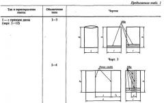
1 , mean: 5.00For the passing of cars in one-way traffic, passing platforms are arranged: on straight sections not more than 100 m apart, and on curves - within the limits of visibility. Platforms for passing are accepted with a width of 2.5 m and a length of at least 12 m, in the case of vehicles with extended bodies on semi-trailers or road trains with trailers and semi-trailers, platforms should be arranged with a length of at least 18 m.
| A) | b) |
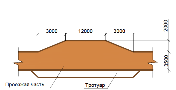 |
Figure 2 - Car siding areas: a) for ordinary vehicles with a sidewalk, b) for vehicles with an extended body
Unloading platforms are taken in the same dimensions as traveling ones, when unloading long loads (trusses, piles, columns, etc.), the dimensions of the platform can be increased to 6 m in width and 35 in length.
Minimum distances from the edge of the road shoulder to other structures on the construction site
Table 2 - Minimum distances from the edge of the curb
Turnaround areas
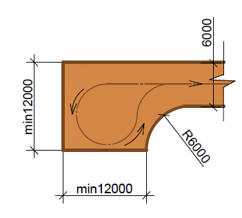
At dead-end entrances, platforms are arranged for turning cars in the forward direction with a size of at least 12x12m, reversal rings with a radius of at least 12m.
| A) | b) |
 | 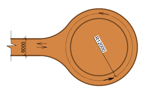 |
| V) | e) |
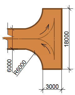 | 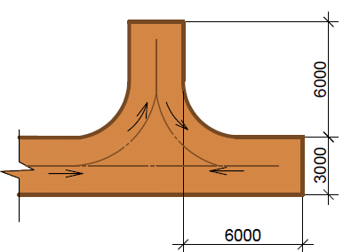 |
Figure 3 - U-turns on dead-end roads: a) for turning cars forward, b) roundabout, c, e) for turning cars in reverse
Temporary road parameters
The parameters of temporary roads are: lane width and carriageway width, number of lanes, curvature radii.
Roadway Width
The width of the carriageway is taken depending on the traffic pattern. For one-way traffic, the width of the carriageway is assumed to be 3 m, for two-way traffic and in places of widening for sidings - 6 m. When using heavy vehicles with a carrying capacity of more than 25 tons, the width of the carriageway is assumed to be up to 8 m. are 12 - 18 m. With a single-lane road, widening up to 5 m is made in the places of its turn.
Figure 4 - Dimensions of the elements of the temporary road: a) for one-way traffic; b) with two-way traffic
Cornering radii
The curvature radii of the road are taken based on the maneuvering properties of vehicles, i.e. the possibility of their rotation when moving forward without the use of reverse gear. The minimum radius of road curvature for conventional dump trucks and flatbed vehicles (with length dimensions up to 10 m) is 12 m; for one-way traffic, the widening of the road at a turn should be at least 5 m. For road trains, the width of the passage is increased to 7 m.
When operating panel carriers, vehicles with trailers, road trains, the curvature radius of the road should be at least 18 m. Roads for the transportation of long structures on vehicles of non-standard dimensions of more than 25 m should have a curve radius of 30 m in plan.
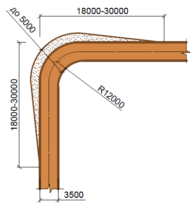
Figure 5 - Scheme of the broadening of the road when turning at an angle of 90 °