L.I.Shmurnova, T.V. Timofeeva, A.I. Kukharchuk
METHODOLOGICAL INSTRUCTIONS
TO COMPLETE COURSE WORK
"ARCHITECTURAL AND CONSTRUCTION DRAWINGS
CIVIL BUILDINGS"
For 2nd year students
specialties "Construction" and "Architecture"
Group ____________________________
Student ___________________________
We then add 4 new glass panels, each using one wire and giving them an offset of 01 and 05 so that they are placed in the center of the frame. This is what your window will look like when you're done editing. I think by now you should understand the power of this system: any combination of frames and panels is possible.
And now we draw the other parts and then move them into place at the same time. To fix this, move the stair line by 5cm by dragging the drawing tool. Now we can draw our plan using wires, then convert them into a sketch, and then create a window. When we repeat this several times, we have the façade completed.
Teacher _____________________
Moscow
Publishing house Russian University Friendship between nations
Peoples' Friendship University of Russia
Shmurnova L.I., Timofeeva T.V., Kukharchuk A.I.
Guidelines for completing the course work “Architectural and construction drawings of civil buildings.” For second year students of the specialty “Construction” and “Architecture”. –M.: RUDN Publishing House, 2009. –18 p.
Now, as before, it's just a matter of turning the parts and moving them into the correct position. The last missing piece is the wall segment that doesn't show up on the floor plan that we need to add. Then we also have to pull out the volume to read the roof and then subtract it.
This building page is now complete. Look at the picture above, we made our door with a frame measuring 5 cm, you remember. But in other windows there are 5cm frames. We've already shown how to create and edit window components using the window editing mode, but we can also edit a basic sketch. Window settings are the same as custom windows, the Window tool only creates a thumbnail. Select our door object and expand it in the tree window. Double click on it and go into edit mode.
Prepared at the Department of Descriptive Geometry and Drawing.
Publishing house of the Peoples' Friendship University of Russia, 2009.
Introduction
Construction drawings of buildings and structures are drawn up according to general rules orthogonal projection. When performing them, it is necessary to be guided by the requirements of ESKD (Unified System of Design Documentation) and SPDS (System project documentation for construction), which complement each other. Thus, when performing architectural and construction drawings, it is necessary to take into account features and conventions , different from those accepted in mechanical engineering drawings:
Sometimes your created object may have problems. For example, an object that was created from a deleted object and an object cannot recalculate its shape. There is no general guide on how to fix such problems because they can have many causes. But the easiest way to solve it is to delete them frequently, and if you haven't deleted your base object, re-create it.
And now that we've gone through the hard work of creating our model, there's a reward: what can we do about it? Moreover, they are updated with every modification of the model. There is an interesting consideration to make before you start exporting. As you have seen, our model becomes increasingly complex, with more relationships between objects. This requires subsequent computational operations that are required, such as trimming to the model. This format saves your entire design, but it discards all relationships and parametric designs and only stores the final shape.
1. in the name and designation of images (types and sections);
2. in sizing;
3. in the image of the thickness of the lines of the visible contour.
From the entire set of engineering and construction drawings, data guidelines include the study of basic architectural and construction drawings: plans, facades, sections. Of the plans, we will only consider floor plans.
Assessing the quality of plumbing by affordable means
Think of it as an "output" file that you can restore at any time from the "main" file. However, exports are still experimental and currently have many restrictions. Focus on technical documentation used for the manufacture of elements requiring plumbing.
Calculation of roof areas and material consumption
Material handling, storage of materials on the roof. Selection, use and maintenance of hand and power tools and work equipment. Alloy of plumbing materials by soft soldering.Demonstrate knowledge of work procedures for creating grooves on uneven roofs
Fabrication, inspection, modification and repair of sub-floors under the roof of complex roofs. Installing grooves on uneven roof surfaces. Design of the shape and craftsmanship of the required element with the development of parts, calculation of material consumption.Manufacturing and assembly of molded and machined parts
Manufacturing replicas of historical plumbing elements. Surface treatment of plumbing elements. The accredited person must indicate the documents that the applicant must submit for examination in accordance with the applicable legal regulations.Course work includes the execution of architectural and construction drawings: a plan of the first floor of a building, a facade, a cross section and a unit, which are performed on sheets of A-1 format. In this case, the plan of the first floor and the facade are made on a scale of 1:100, the section on a scale of 1:50, and the unit on a scale of 1:10.
Fig.1. Arrangement of images on the sheet.
Before starting the self-assessment, the applicant must be familiar with the workplace and the safety, health and fire protection requirements. Medical training required. Test Entry Conditions: The applicant for this vocational qualification must be a holder of a full vocational qualification for a construction plumber, which must be documented.
The applicant must be equipped with his own work clothing, footwear and personal protective equipment appropriate to the work performed. The test can be performed either on the training roof or on the property. When testing professional qualifications, the following standards and rules must be observed.
GOST R21.1101-92 (SPDS) establishes uniform forms, sizes and procedures for filling out main inscriptions on the drawings of student coursework and diploma projects.
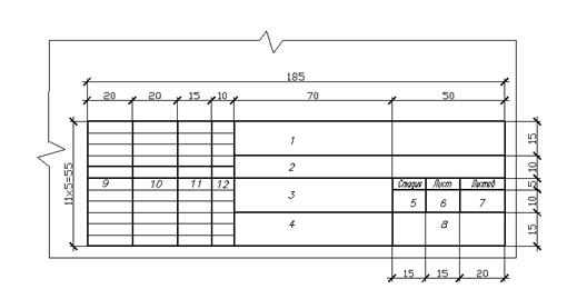
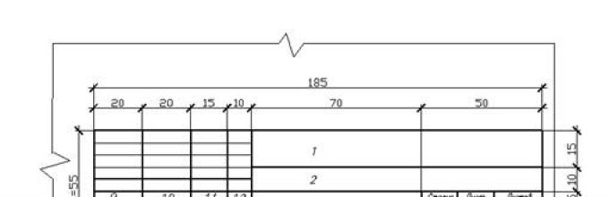
Fig.2. Main inscription on sheets of building drawings.
In column 1 - the name of the department, the designation of the course work (CR), the option number. Capital font, size 7.
Practical testing of individual competencies requires assessment of work organization, compliance with established process procedures, selection and adherence to work procedures, selection and use of tools, equipment and work equipment. An integral part of the applicant's assessment is the assessment of the quality of the work done.
Due to the nature of certain audit activities professional competencies, the tender must provide assistance from other persons or means of mechanization. An authorized person must provide handling equipment for transporting materials to the roof, including their operation.
In column 2 - the name of the project, work. Capital font, size 5.
Column 3 contains the name of the task. Capital font, size 5.
In column 4 - the name of the images placed on this sheet. Capital font, size 3.5.
In column 5 - U (training drawings).
Column 6 contains the serial number of the sheet. On documents consisting of one sheet, the column is not filled in.
Column 7 shows the total number of sheets of the CD.
Column 8 contains the group number and the name of the university. Lowercase font, size 5.
In column 9 – from bottom to top – “Student”, “Accepted”, “Consultant”. Lowercase font, size 3.5
In columns 10, 11, 12, respectively, surname, signature, date.
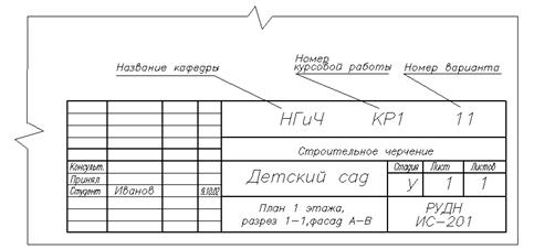
Fig.3. An example of filling out the title block on sheets of architectural and construction drawings.
When making architectural and construction drawings, it is advisable to use a narrow architectural font, which is simple, clear in outline and easy to read (see Fig. 4).
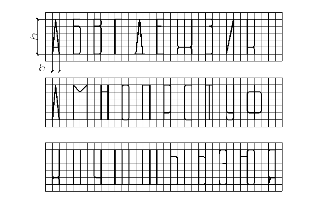
Fig.4. Architectural (narrow) font.
The width of the letters is taken in the range from 1/4 to 1/8 of the height. The distance between letters is no less than half their width. In headings, the distance between letters in words increases to 4/5 of the letter height. The stroke thickness of letters is 1/15 – 1/20 of their height.
Initially, all drawings are made in pencil in fine lines. After the teacher checks the drawings, the work is outlined in ink. Students majoring in Architecture are cleaning the façade.
Before starting work, you need to familiarize yourself with the details of the individual task.
The assignment contains schematic drawings of plans, a facade, a section of the building, linking window and doorways, location of the staircase and sanitary equipment. The appendix to the graphic part indicates the materials and thickness of load-bearing external and internal walls, partitions, dimensions of window and door openings. The section shows the elevations of the roof, interfloor slabs, and the depth of the foundation base.
The names of the facade, floor plan, section are located above the image and are not underlined.
Drawing a plan 1st floor of the building.
It is recommended to begin the graphic part of the course work by drawing a plan of the first floor.
Building floor plan - This is a horizontal section made at the level of window and door openings. The building plan gives an idea of the shape of the building in plan and the relative position of its individual rooms.
Sequence of drawing a plan .
1. Carry out longitudinal and transverse coordination axes. These axes pass along load-bearing structures (columns and main walls), i.e. in the places where the foundations will be located. The vertical axes are designated in Arabic numerals from left to right, and the horizontal axes from bottom to top in letters of the Russian alphabet (except for the letters E, J, O, Z, Ts, Ch, Shch, b, b, y) in circles with a diameter of 8-12 mm. Gaps in digital and alphabetic (except for those indicated) designations are not allowed.
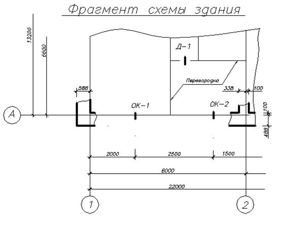
Fig.5. Fragment of the building diagram.
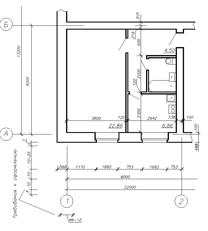
Fig.6. Fragment of the building plan.
2. Draw the contours of external and internal load-bearing walls and columns (if any). In this case, the axes follow the contour of the wall, are either shifted inside the wall by 100 mm, or pass through the middle of the wall. External and internal load-bearing walls have a thickness of 2 or 1.5 bricks, respectively. This means that 2 or 1.5 bricks (lengthwise) are laid across the wall (see Fig. 7,8)
IN course work it is planned to make walls from modular bricks with dimensions 288 X 138 X 63 and mortar joint thickness t=12 mm.
Then the thickness of a wall of two bricks will be:
288 +12 +288=588 mm.
The wall thickness of 1.5 bricks will be:
288 +12 +138=438 mm
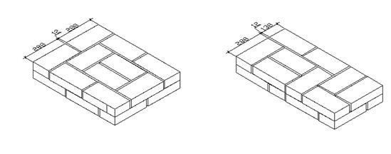
Fig.7 Wall of 2 bricks Fig.8 Wall of 1.5 bricks
3. Draw window and door openings along the external walls. According to the terms of the assignment, these openings must be made with quarters.
Quarter - this is a protrusion in the upper and side parts of the openings of brick walls, which reduces airflow and facilitates the fastening of door and window blocks.
Quarter openings are made in buildings where people may be near the window openings.
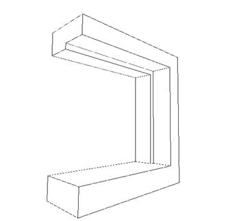
Fig.9. Quarter for modular bricks.
The assignment specifies the dimensions of the door and window units. The diagram of the first floor plan shows the location of the middle of the window and door (external) openings. On the ground floor plan, it is necessary to mark a chain of dimensions of window and door openings along the contour of the entire building, taking into account the quarters. and link these openings to coordination axes.
Example. The width of the window block is set to b=1812 mm. On the plan you must indicate the size taking into account the quarter: 1812-75x2=1662
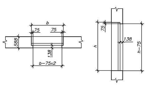
Rice. 10. Window dimensions including quarter
Draw the contours of the partitions. The thickness of the partitions is indicated in the text of the task. If the layout of the partitions is not indicated on the plan diagram, you can use a linear scale. It is necessary to indicate which way the doors open. According to fire safety requirements external doors open outside , and the doors to the apartment go inside the apartment. The doors on the plan should be shown in the open position at an angle of 30˚ (see Fig. 11).
4. Draw out sanitary fixtures, kitchen equipment, ventilation ducts. The latter are located in the internal walls. (see Fig. 12,13).
5. Draw flights of stairs and landings. On the plan of the first floor staircase, the ground (lower) flight and half of the lower main flight are shown diagonally (this is how they conventionally show that this flight falls into the section). On the plan of the second floor, the flights of stairs are depicted in full, because the building is two-story. The direction of rise is indicated by an arrow.
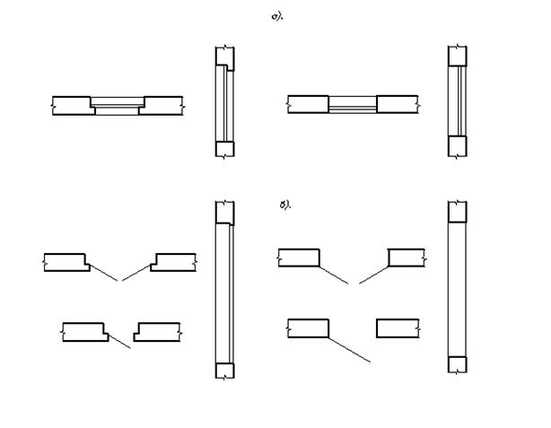
Fig. 11. Conditional image on plan and section
a) windows, b) doors.
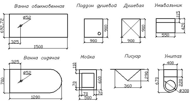
Rice. 12. Legend elements of plumbing fixtures.
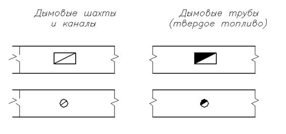
Rice. 13. Symbols of ventilation elements.
6. Put down the dimensions. On the floor plan, three closed dimensional chains are placed along the outer contour:
a) the dimensions of the partitions, window and door openings (the distance from the first dimensional chain to the outer wall is taken at least 15-20 mm so as not to make reading the drawing difficult);
b) the distance between the coordination axes;
c) the distance between the extreme coordination axes.
Dimensions on construction drawings are applied in accordance with GOST 2307-68, taking into account the requirements of GOST 21.1501-92. So, instead of arrows they use serifs in the form of a short stroke drawn basic a contour line slanted to the right at an angle of 45˚ to the dimension line. If there is not enough space, serifs can be replaced with dots.
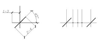
Fig. 14. Serif sizes.
If the task has several window and door openings of the same size, put down the dimensions everyone , regardless of their number.
Inside the building, the plan must show the dimensions of the rooms between the internal contours of the walls and partitions, the thickness of the walls and partitions and indicate the area separate rooms V square meters with two decimal places. The area is written in the lower right corner and underlined (see Fig. 6).
DRAWING THE SECTION.
By cut called an image of a building made by a secant frontal or profile plane.
The cutting plane should pass through the most important parts of the building (along the staircase, window and door openings, etc.). Therefore, a stepped incision is sometimes performed. It should be borne in mind that the section plane passes along the marches closest to the observer (see Fig. 16).
The direction of the secant plane in the section is indicated on the plan of the 1st floor. On the cut itself there is an inscription: SECTION 1-1 or SECTION AA. When making a cut, the cutting plane is not carried out along columns, along walls, partitions, roof beams and ceilings.
Sequence of drawing a section.
1. Conduct vertical modular coordination axes load-bearing walls in accordance with the plan and direction of the cut.
2. Outline the contours of walls and partitions.
Draw horizontal lines of the ground level, the base of the foundation, the finished floor of the floors, the bottom of the roof slabs of the upper floor, the top of the attic floor, the contour of the roof, window and door openings.
The floor of the first floor of interfloor and attic floors drawn with one continuous main line, regardless of the number of layers in their structures.
3. Height interior spaces and the main external structural elements are indicated in numerical marks. In construction, the 0.000 mark is conventionally taken to be the level mark of the finished floor of the 1st floor.
Mark – this is the height distance from the zero level. It is measured in meters with three decimal places. All elements located below the floor level of the 1st floor (basements, foundations, etc.) are marked with a minus sign, and above the floor level of the 1st floor - with a plus sign. If necessary, the marks are accompanied by the appropriate inscriptions: Ur.ch.p. – level of the finished floor, Ur.z. - ground level.
4. Draw the stairs.
Stairs used for everyday use are called main ones. The internal main staircases consist from marches And landings . Flights of stairs consist of steps that rest on inclined beams called stringers . The steps consist of tread And riser . Step height ( riser ) must be no more 170 mm, and the width of the step ( tread) no less 260 mm.
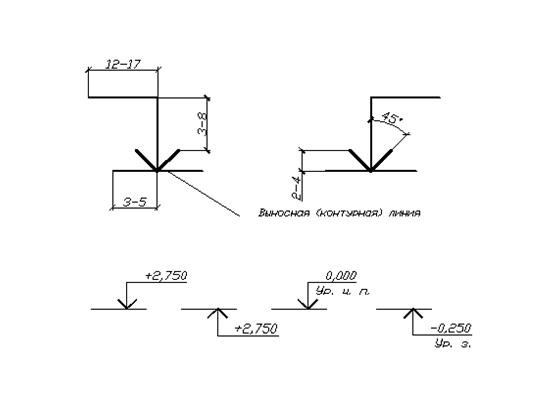
Fig. 15. Sizes of marks and examples of marking.
Graphic breakdown stairs.
1. The slopes of marches are usually taken equal to 1:2. Let us take the width of the tread to be 300 mm, and the height of the riser to be in the range from 150 to 170 mm. In this case, the width of the first and last steps of each march, which are called frieze, take in the range of 220-260 mm.
2. The width of the landings is given in the individual assignment. Distance E from the plane of the wall to the first step must be at least 1200 mm. Therefore, in buildings with a floor height of 3.6 m, the width of the frieze steps is taken to be 250 mm, and with a lower floor height, the width of the frieze steps is 300 mm.
There should be a distance of 100-200 mm between the marches - the gap required for the passage of a fire hose.
The graphical breakdown of the staircase is based on the height of the floor and determines the level of the intermediate platform (at half the height of the floor). Draw vertical lines according to the number of steps in the plan. The distance between the lines is equal to the width of the step and is 300 m
Figure 16 shows an example of the breakdown of a two-flight staircase in a building with a floor height H = 3.1 m. The height of each flight is H/2 = 1.55 m. The number of risers in one flight is 1550/155 = 10.
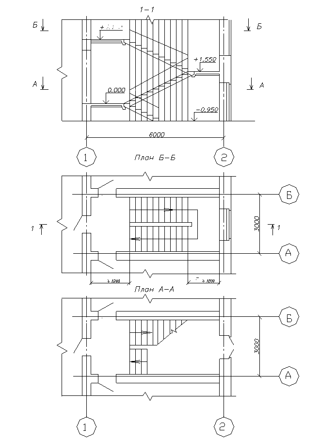
Fig16. Graphic breakdown of the stairs
The number of treads is one less, because The width of the upper frieze step is included in the width of the platform. The layout of the march (the length of its horizontal projection) is equal to
d=300(n-1)=300x9=2700 mm.
3. Enter the following dimensions:
· marks of ground level, finished floor, floors and platforms;
bottom marks load-bearing structures coatings;
· mark of the bottom of the supporting part of structural elements embedded in the wall (balconies, canopies, etc.)
· marks of the top of walls, cornices;
· dimensions and alignment (in height) of window and door openings in external walls;
· the thickness of the walls and their connection to the coordination axes.
SECTION 1-1
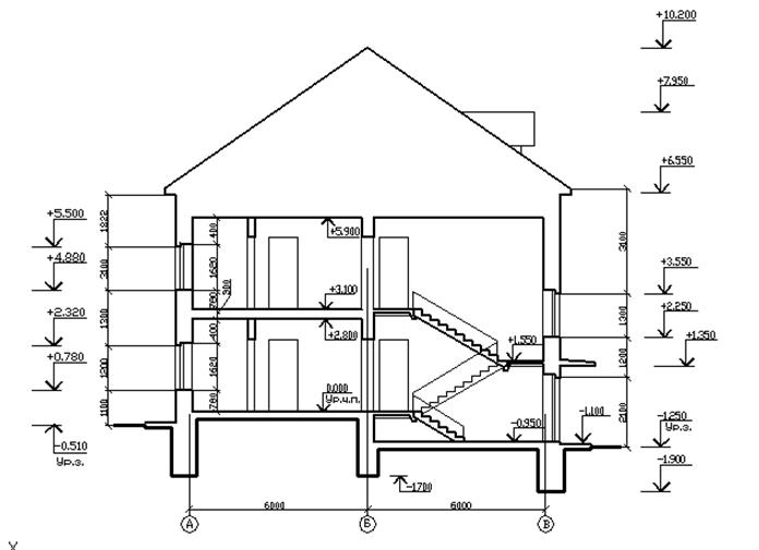
Rice. 17. An example of making a section of a building.
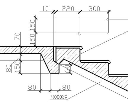
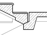
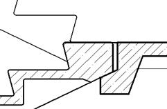
Rice. 18. Options for the staircase assembly.
FACADES.
Facade – this is the projection of the building onto the vertical (front) plane.
The facade gives an idea of appearance building. The façade of a building facing the main street is called main. The facade can be end or courtyard. Above the facade there is a corresponding inscription of the type “Facade 1-6” in accordance with the extreme axes from left to right (see Fig. 19.) The facade should be simple and beautiful. In some cases, the drawing may show the texture of the walls (the material from which the wall decoration is made).
The façade shows:
· extreme coordination axes of the building;
· marks of the ground level, entrance platforms, top of walls, bottom and top of openings and facade elements located at different levels (canopies, remote vestibules);
· window and door frames, balcony railings (if any), ventilation and chimneys on the roof.
Marks are not placed on facades made with a wash.
After completion in pencil and checking by the teacher, the drawings must be outlined in ink. The thickness of the stroke is given in Table 1.
Table 1.
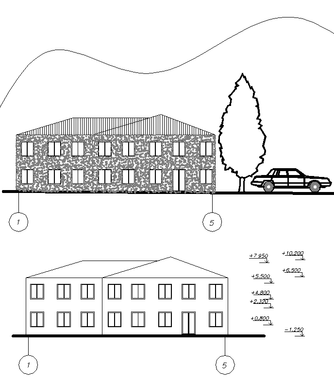
Rice. 19. Examples of facades.
An image in the form of a mental section is called a horizontal plane passing at the level of window and door openings. In Fig. 1.1 a, 6, c show various options for designing plans.
The plan of the building gives an idea of its size and shape and includes the relative position of individual rooms. The building plan shows window and door openings, the location of stairs, partitions and main walls, built-in wardrobes, sanitary equipment, etc.
If the plan, facade and section of the building can be placed on one sheet, then the plan is placed under the facade in projection connection with it.
However, due to the large size of the images, the plans are usually placed on separate sheets, with their long side placed along the long side of the sheet.
Depending on the purpose, there are floor plans, basement, attic, roof plans, and installation plans, which are diagrams of the arrangement of elements of prefabricated structures (foundations, floors, frames, etc.). In the names placed on the drawings, the following terminology is observed: “Plan at level 0.000”, “Plan of 1-16 floors”, “Plan of the technical underground”, etc.
All structural elements included in the section (walls, pillars, columns) are outlined with a solid main line.
Fig.1.1. Various design options for the building plan
On the drawings of the plans the following is indicated: ; chains of external and internal dimensions, including the thickness of walls, partitions, dimensions of window and door openings (internal dimensions are applied inside the drawing, external dimensions - outside); area of premises; level marks for finished floors (if floors are located at different levels); names of premises or their numbering (when creating a table of premises in the drawing); built-in and sanitary equipment.
The building plan is drawn in the following order:
a) draw longitudinal and transverse coordination axes;
b) draw out all external and internal walls, partitions and columns, if any
c) make a breakdown of window and door openings in external and internal walls and partitions, conditionally show the opening of doors, draw sanitary equipment and draw the necessary extension and dimension lines;
d) put all dimensions on the drawing, make appropriate inscriptions and check the drawing made in thin lines;
e) after correcting and finalizing the missing places, they begin the final tracing.
Floor plans in demonstration drawings must carry comprehensive information about the compositional solution of the object, the structure of the internal space and the connection of the premises. Therefore, drawings of such plans should not be overloaded with dimensions, markings of elements and other designations.
On demonstration drawings of plans, coordination axes are drawn and the main ones are indicated dimensions. Coordination axes should not be drawn as a dash-dotted line along the entire length of the walls until they intersect with the dimension lines, as is done in working drawings.
To explain the purpose of the premises, the corresponding names are written in each of them or designated by a serial number, and the names are entered into the table - an explication of the premises. The plans must indicate the locations of the sections and sections shown in the drawings.
On the plan illustrative drawings depict in detail everything that relates to planning decision: external and internal doors with the direction of their opening, sanitary equipment, if any - stoves or fireplaces, show the arrangement of furniture in the main rooms.
On the ground floor plans depict elements of the general plan directly adjacent to the building: paths, landscaping techniques, small forms. In this case, the axes and dimension lines should be placed as far as possible from the drawing so that they do not interfere with the perception of the main planning solution.
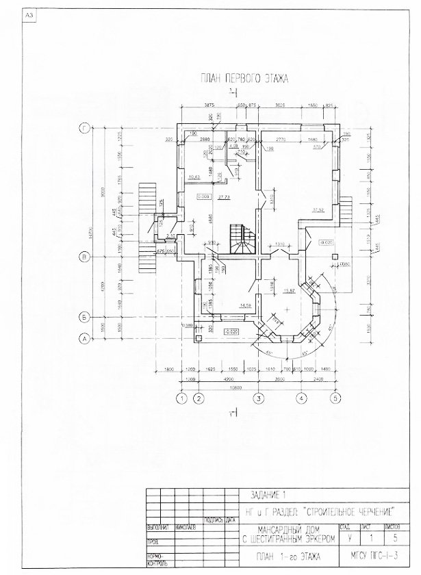
Fig.1.2. An example of a plan for the 1st floor of a building
Saturation degree architectural plans details depend on the scale of the drawing. The larger the scale, the more attention it requires to the development of details that specify the compositional and planning solution and decorate the drawing.
When architectural and construction plans are full of details, it is important to find the most expressive graphic way of their implementation, which reveals the architectural and constructive construction of the plan and its structural merit. These requirements are best met by filling the sections with black ink, which gives a clear image. At the same time, all other elements of the plan are outlined with a thin black or colored line (see Fig. 1.1 a).
If a plan or fragment of a plan is completed in on a large scale(1:50 or more), then the black ink fill will be too “heavy” and rough. In this case, it is better to outline all sections of the walls with a 1.5-2 mm black line (see Fig. 1.1, b).
Various graphic line methods are also used to depict walls and their horizontal sections (see Fig. 1.1, c). An architectural and construction drawing of a plan can not only be made in one color, but also have different coloring of parts in watercolor, tempera or gouache, if this is necessary for graphic connection with other project drawings.
Furniture and equipment on the plan should be depicted in such a way that these elements appear in the drawing to go into another horizontal plane located below the section. The stroke line of these elements can be black, slightly drawn or colored. In Fig. Figure 1.2 shows an example of a floor plan for a residential building.